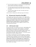


Maintenance
General Information
4
4-7
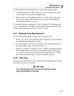
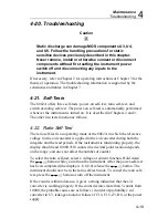
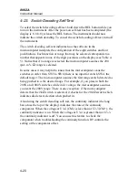
Elastomeric Strip
Green Power
Switch Cap
AC Shield
Remove before removing
Main PCB. When reassembling,
install shield after installing
Main PCB.
Pry fuse out from the side.
Backup Fuse F2
dy32c.eps
Figure 4-1. CALIBRATION AND BACKUP FUSE (F2) ACCESS
4-7.
Main PCB Access
Use the following procedure to gain access to the main pcb:
1.
Remove the screw in the center of the ac shield and remove the shield.
2.
Using your index finger, lift up the lower right corner of the main pcb
until it is free. Then pull the pcb to the right until it clears the shelf under
the buttons.
Summary of Contents for 8062A
Page 4: ......
Page 8: ...8062A Instruction Manual iv...
Page 10: ...8062A Instruction Manual vi...
Page 14: ...8062A Instruction Manual 1 2...
Page 24: ...8062A Instruction Manual 2 2...
Page 50: ...8062A Instruction Manual 2 28...
Page 52: ...8062A Instruction Manual 3 2...
Page 62: ...8062A Instruction Manual 3 12...
Page 64: ...8062A Instruction Manual 4 2...
Page 90: ...8062A Instruction Manual 4 28...
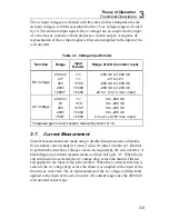
Page 92: ...8062A Instruction Manual 5 2...
Page 102: ...8062A Instruction Manual 5 12 8062A 4031 iv39c eps Figure 5 2 A1 Main PCB Assembly...
Page 106: ...8062A Instruction Manual 6 2...
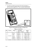
Page 108: ...8062A Instruction Manual 6 4 dy55c eps Figure 6 1 Accessories...
Page 118: ...8062A Instruction Manual 7 2...
Page 122: ...8062A Instruction Manual 7 6...
Page 123: ...8062A Instruction Manual 7 7 8062A 1201 iu46c eps Figure 7 5 A1 Main PCB Schmatic Diagram...
Page 124: ...8062A Instruction Manual 7 8 8060A 1003 iu61f eps Figure 7 6 A3 RMS PCB Schmatic Diagram...


