


8062A
Instruction Manual
3-6
Read
2V dc
9R
R
C
AZ
C
Integ
200 mV
dc
Integ
AZ
+
+
+
+
Reference
Voltage
Integrator Gain
Integrator
Comparators
AZ
Integ or Read
To Digital
Control Logic
Buffer Amp
±
Unkown
Input Voltage
Internal to the MAC
dy26f.eps
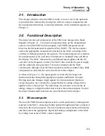
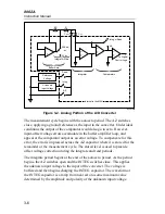
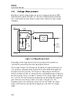
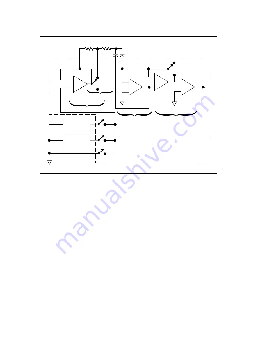
Figure 3-2. Analog Portion of the A/D Converter
The measurement cycle begins with the autozero period. The AZ switches
close, applying a ground reference as the input to the converter. Under ideal
conditions the output of the comparator would also go to zero. However,
input-offset voltage errors accumulate in the buffer amplifier loop, and
appear at the comparator output as an error voltage. To compensate for this
error, the error is impressed across the AZ capacitor where it is stored for the
remainder of the measurement cycle. The stored level is used to provide
offset voltage correction during the integrate and read periods.
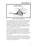
The integrate period begins at the end of the autozero period. As the period
begins, the AZ switches open and the INTEG switches close. This applies
the unknown input voltage to the input of the converter. The voltage is
buffered and then begins charging the INTEG capacitor. The waveform at
the INTEG capacitor is a ramp from near zero to some maximum value
determined by the amplitude and polarity of the unknown input voltage.
Summary of Contents for 8062A
Page 4: ......
Page 8: ...8062A Instruction Manual iv...
Page 10: ...8062A Instruction Manual vi...
Page 14: ...8062A Instruction Manual 1 2...
Page 24: ...8062A Instruction Manual 2 2...
Page 50: ...8062A Instruction Manual 2 28...
Page 52: ...8062A Instruction Manual 3 2...
Page 62: ...8062A Instruction Manual 3 12...
Page 64: ...8062A Instruction Manual 4 2...
Page 90: ...8062A Instruction Manual 4 28...
Page 92: ...8062A Instruction Manual 5 2...
Page 102: ...8062A Instruction Manual 5 12 8062A 4031 iv39c eps Figure 5 2 A1 Main PCB Assembly...
Page 106: ...8062A Instruction Manual 6 2...
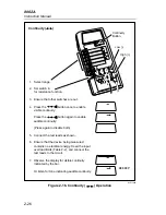
Page 108: ...8062A Instruction Manual 6 4 dy55c eps Figure 6 1 Accessories...
Page 118: ...8062A Instruction Manual 7 2...
Page 122: ...8062A Instruction Manual 7 6...
Page 123: ...8062A Instruction Manual 7 7 8062A 1201 iu46c eps Figure 7 5 A1 Main PCB Schmatic Diagram...
Page 124: ...8062A Instruction Manual 7 8 8060A 1003 iu61f eps Figure 7 6 A3 RMS PCB Schmatic Diagram...


