


Operation Instructions
Fuse Replacement
2
2-5
You can measure the voltage of your battery by using the following
procedure:
1.
Select the dc voltage function and the 20V range.
2.
Locate the opening for the battery eliminator jack on the right side of the
instrument to the right of the display. Touch the red (V
Ω
S) probe tip to
the side contact (not the center pin). Be sure you do not short the battery
by shorting the side contact to the center pin. Battery voltage should be
between 5.2V to 10V for proper operation. If the voltage is less, the
battery should be replaced.
2-4. Fuse
Replacement
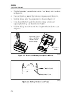
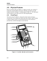
There are two fuses located at the right side of the battery compartment
(refer to Figure 2-2 or examine your instrument). The fuse at the far right is
F1. Fuse F1, 2A/250V, protects the current input from an input overload.
The other fuse is a spare fuse for F1. When you purchase your instrument, F1
should be installed and the spare fuse should be in one of the two slots next
to it. The larger slot is for the American-style fuse, and the smaller slot is for
the European-style fuse (either style fuse fits in the installation
compartment).
If you need to replace F1, use the tip of a test lead to push the fuse forward
from the end and then up to release. Replace F1 with the appropriate
2A/250V fuse; American-style: fast-acting, type AGX2, 1/4 x 1”, Fluke PN
376582; European-style: 5 x20 mm, Fluke PN 460972. Do not use makeshift
fuses or short-circuit the fuseholder.
There is another fuse, F2, 3A/600V, which also protects the current input.
The instrument cover must be removed to replace F2. This procedure is
described in Chapter 4 and should only be done by a person qualified to
service the instrument.
The following steps provide a quick and easy way to check the condition of
both fuses F1 and F2:
1.
Select the resistance function and the 2 k
Ω
range.
2.
Touch the red test lead tip to the A input jack so that the V
Ω
S input and
the A input are shorted together.
3.
If the display reads .1000
±
.0100 k
Ω
, both fuses are good.
4.
If the display read OL, one or both fuses need replacement.
Summary of Contents for 8062A
Page 4: ......
Page 8: ...8062A Instruction Manual iv...
Page 10: ...8062A Instruction Manual vi...
Page 14: ...8062A Instruction Manual 1 2...
Page 24: ...8062A Instruction Manual 2 2...
Page 50: ...8062A Instruction Manual 2 28...
Page 52: ...8062A Instruction Manual 3 2...
Page 62: ...8062A Instruction Manual 3 12...
Page 64: ...8062A Instruction Manual 4 2...
Page 90: ...8062A Instruction Manual 4 28...
Page 92: ...8062A Instruction Manual 5 2...
Page 102: ...8062A Instruction Manual 5 12 8062A 4031 iv39c eps Figure 5 2 A1 Main PCB Assembly...
Page 106: ...8062A Instruction Manual 6 2...
Page 108: ...8062A Instruction Manual 6 4 dy55c eps Figure 6 1 Accessories...
Page 118: ...8062A Instruction Manual 7 2...
Page 122: ...8062A Instruction Manual 7 6...
Page 123: ...8062A Instruction Manual 7 7 8062A 1201 iu46c eps Figure 7 5 A1 Main PCB Schmatic Diagram...
Page 124: ...8062A Instruction Manual 7 8 8060A 1003 iu61f eps Figure 7 6 A3 RMS PCB Schmatic Diagram...


