


8062A
Instruction Manual
3-8
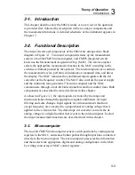
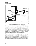
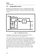
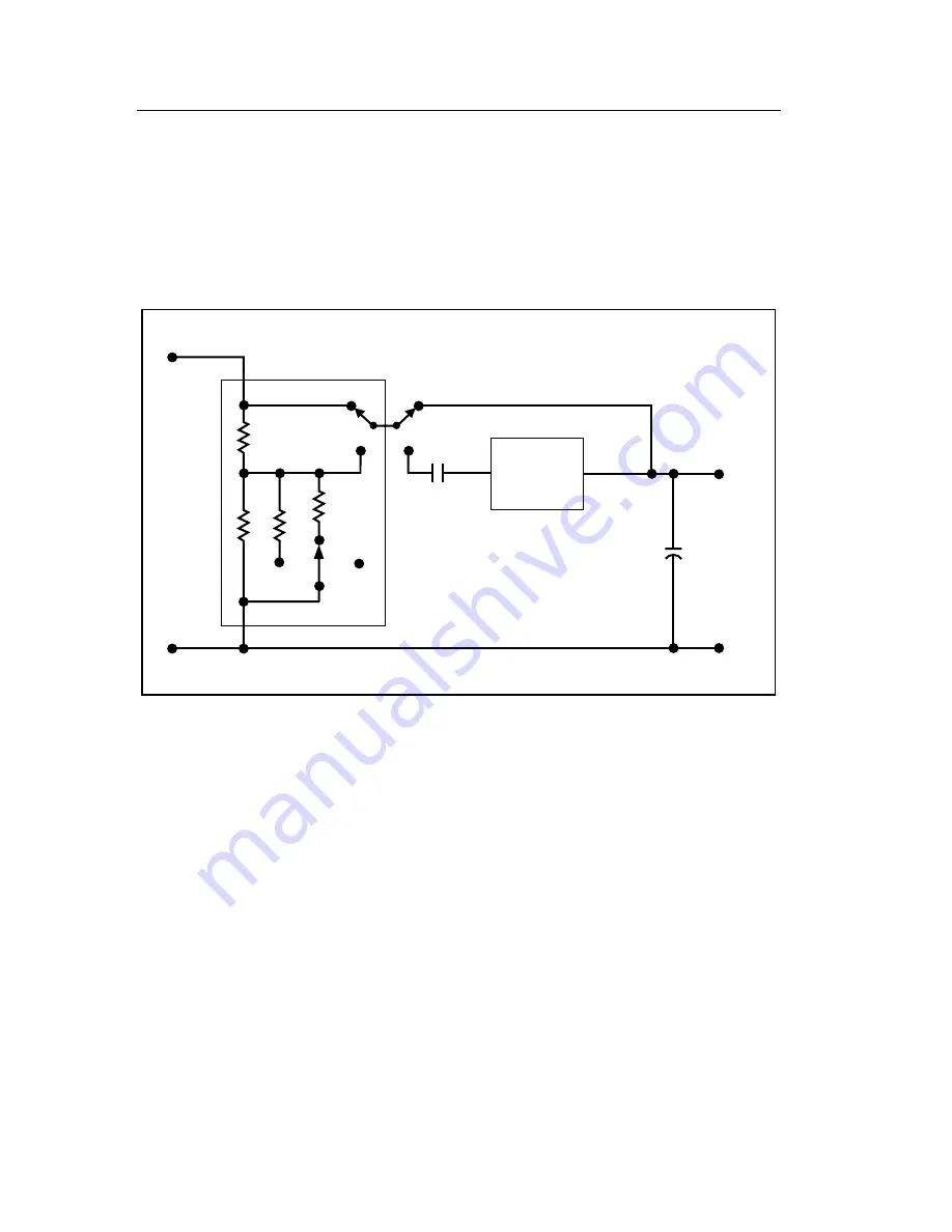
3-6. Voltage
Measurement
Both the ac and dc voltage ranges use an over-voltage-protected 10 M
Ω
input divider as shown in Figure 3-4. The over-voltage protection includes
two 2-watt fusible resistors and four metal-oxide varistors for high voltage
clamping.
V/
Ω
Voltage
Divider
÷
1
DC
AC
True RMS
AC
Converter
Inputs
to A/D
Converter
Common
LO
HI
÷
10
÷
100
÷
1000
÷
100
÷
10
÷
1000
dy28f.eps
Figure 3-4. Voltage Measurement
Depending on the range selected, lower leg resistors of the divider are
connected to ground to perform the input signal division.
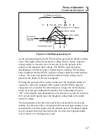
The dc input voltages for all ranges are divided by the appropriate factor of
10 to produce a proportional dc signal which is then filtered and applied to
the input to the a/d converter. The dc and ac voltage ranges and division
factors are listed in Table 3-1 along with the corresponding range of inputs to
the a/d converter. Notice in Table 3-1 that the 2V dc voltage range is divided
by 1 (not 10). The microcomputer compensates by decreasing the integrator
gain in the a/d converter by a factor of 10 (refer to Figure 3-2). The
integrator gain is also reduced by a factor of 10 in the 1000V dc voltage
range, which uses the same divider arrangement as the 200V dc voltage
range.
Summary of Contents for 8062A
Page 4: ......
Page 8: ...8062A Instruction Manual iv...
Page 10: ...8062A Instruction Manual vi...
Page 14: ...8062A Instruction Manual 1 2...
Page 24: ...8062A Instruction Manual 2 2...
Page 50: ...8062A Instruction Manual 2 28...
Page 52: ...8062A Instruction Manual 3 2...
Page 62: ...8062A Instruction Manual 3 12...
Page 64: ...8062A Instruction Manual 4 2...
Page 90: ...8062A Instruction Manual 4 28...
Page 92: ...8062A Instruction Manual 5 2...
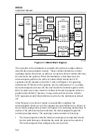
Page 102: ...8062A Instruction Manual 5 12 8062A 4031 iv39c eps Figure 5 2 A1 Main PCB Assembly...
Page 106: ...8062A Instruction Manual 6 2...
Page 108: ...8062A Instruction Manual 6 4 dy55c eps Figure 6 1 Accessories...
Page 118: ...8062A Instruction Manual 7 2...
Page 122: ...8062A Instruction Manual 7 6...
Page 123: ...8062A Instruction Manual 7 7 8062A 1201 iu46c eps Figure 7 5 A1 Main PCB Schmatic Diagram...
Page 124: ...8062A Instruction Manual 7 8 8060A 1003 iu61f eps Figure 7 6 A3 RMS PCB Schmatic Diagram...


