


8062A
Instruction Manual
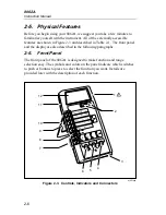
2-20
2-19. Autoranging Kilohms
Although it is not indicated on the front panel, there is an additional
autoranging range available: the autoranging k
Ω
range, which consists of 2
k
Ω
, 20 k
Ω
, and 300 k
Ω
ranges. To select this range, you must
simultaneously press the M
Ω
and the 200
Ω
switches as shown in Figure 2-
13. Like the autoranging M
Ω
ranges, the autoranging k
Ω
ranges have enough
voltage to turn on semiconductor junctions. Note that the use of the relative
function with the autoranging k
Ω
ranges is restricted to the autoranging k
Ω
ranges. Refer to the description of the relative function for more information.
The autoranging k
Ω
has the same decrease in resolution (see Table 2-3) and
the same display hysteresis as the autoranging M
Ω
.
2000mA
A
A
COMMON
V
Ω
S
V
Ω
S
200mA
200
200k
200
µ
A
DC
AC
200mV
200
Ω
20mA
20
20k
2mA
2
2k
1000 DC
750 AC
M
Ω
REL
1000V DC
750V AC
MAX
2A MAX
500V MAX
!
!
Low (-)
High (+)
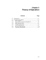
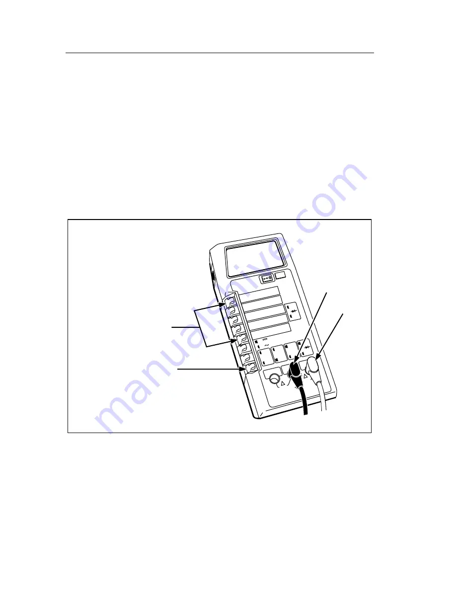
1. Push both the M
Ω
and
200
Ω
switches at the
same time to select the
K
Ω
autorange.
2. Press switch in to select
resistance function and
measure resistance as
described in Figure 2-12.
dy14f.eps
Figure 2-13. Selection of Autoranging Kilohms
Summary of Contents for 8062A
Page 4: ......
Page 8: ...8062A Instruction Manual iv...
Page 10: ...8062A Instruction Manual vi...
Page 14: ...8062A Instruction Manual 1 2...
Page 24: ...8062A Instruction Manual 2 2...
Page 50: ...8062A Instruction Manual 2 28...
Page 52: ...8062A Instruction Manual 3 2...
Page 62: ...8062A Instruction Manual 3 12...
Page 64: ...8062A Instruction Manual 4 2...
Page 90: ...8062A Instruction Manual 4 28...
Page 92: ...8062A Instruction Manual 5 2...
Page 102: ...8062A Instruction Manual 5 12 8062A 4031 iv39c eps Figure 5 2 A1 Main PCB Assembly...
Page 106: ...8062A Instruction Manual 6 2...
Page 108: ...8062A Instruction Manual 6 4 dy55c eps Figure 6 1 Accessories...
Page 118: ...8062A Instruction Manual 7 2...
Page 122: ...8062A Instruction Manual 7 6...
Page 123: ...8062A Instruction Manual 7 7 8062A 1201 iu46c eps Figure 7 5 A1 Main PCB Schmatic Diagram...
Page 124: ...8062A Instruction Manual 7 8 8060A 1003 iu61f eps Figure 7 6 A3 RMS PCB Schmatic Diagram...


