


Theory of Operation
Functional Description
3
3-7
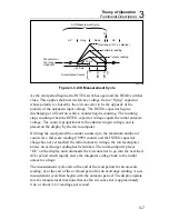
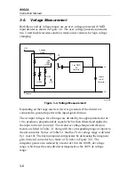
A/D Measurement Cycle
AZ
AZ
OL
Integ
100 ms
400 ms
Read
Overrange (“OL” on display)
Fullscale reading
Accumulated Counts
Waveform at
the Integ
Capacitor
OL
19999
10000
0
1
/
2
scale reading
dy27f.eps
Figure 3-3. A/D Measurement Cycle
As the read period begins, the INTEG switches open and the READ switches
close. This applies the known reference voltage from a “flying” capacitor
whose polarity is chosen by the a/d converter to be the opposite of the
polarity of the unknown input voltage. The INTEG capacitor begins
discharging at a fixed rate while a counter begins counting. The counting
stops counting when the INTEG capacitor voltage equals the initial autozero
voltage. The count is proportional to the unknown input voltage, and is
placed on the display by the microcomputer.
If during the read period the counter counts up to the maximum number of
counts for a full-scale reading (19999 counts) and the INTEG capacitor
charge has not yet reached the initial autozero voltage, the microcomputer
knows an overrange reading has been taken. The microcomputer places
“OL” on the display and commands the a/d converter to go into the overload
(OL) period which rapidly slews the integrator voltage back to the initial
autozero voltage.
The measurement cycle ends at the end of the read period for an on-scale
reading, or at the end of the overload period for an overrange reading. A new
measurement cycle then begins with the autozero period. The display update
rate for measurement functions that use the a/d converter is approximately
0.4s, or about 2-1/2 readings per second.
Summary of Contents for 8062A
Page 4: ......
Page 8: ...8062A Instruction Manual iv...
Page 10: ...8062A Instruction Manual vi...
Page 14: ...8062A Instruction Manual 1 2...
Page 24: ...8062A Instruction Manual 2 2...
Page 50: ...8062A Instruction Manual 2 28...
Page 52: ...8062A Instruction Manual 3 2...
Page 62: ...8062A Instruction Manual 3 12...
Page 64: ...8062A Instruction Manual 4 2...
Page 90: ...8062A Instruction Manual 4 28...
Page 92: ...8062A Instruction Manual 5 2...
Page 102: ...8062A Instruction Manual 5 12 8062A 4031 iv39c eps Figure 5 2 A1 Main PCB Assembly...
Page 106: ...8062A Instruction Manual 6 2...
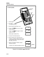
Page 108: ...8062A Instruction Manual 6 4 dy55c eps Figure 6 1 Accessories...
Page 118: ...8062A Instruction Manual 7 2...
Page 122: ...8062A Instruction Manual 7 6...
Page 123: ...8062A Instruction Manual 7 7 8062A 1201 iu46c eps Figure 7 5 A1 Main PCB Schmatic Diagram...
Page 124: ...8062A Instruction Manual 7 8 8060A 1003 iu61f eps Figure 7 6 A3 RMS PCB Schmatic Diagram...


