


8062A
Instruction Manual
2-12
complex ac signals. Since rms is the dc equivalent to the original waveform,
it can be used in the relationships derived from Ohm’s law (E = I x R), and
provides a reliable basis for comparing dissimilar waveforms.
Most meters in use today have average-responding ac converters rather than
true rms ac converters like the 8062A. Usually the gain in average-
responding meters is adjusted so that the reading gives the rms value,
provided the input signal is a harmonic-free sinusoid. However, if the signal
is not sinusoidal, the average-responding meter does not give correct rms
readings.
The 8062A ac converter actually calculates the rms value through analog
computation. This means that 8062A readings are accurate rms values not
only for harmonic-free sinusoids, but also for mixed frequencies, modulated
signals, square waves, sawtooths, 10%-duty-cycle rectangular pulses, etc.
2-13. AC-Coupled AC Measurements
Input signals are ac-coupled in the ac functions. One of the major advantages
of ac-coupling is that ripple measurements can be made on power supplies,
phone lines, etc. Ripple measurements cannot be made with dc-coupling.
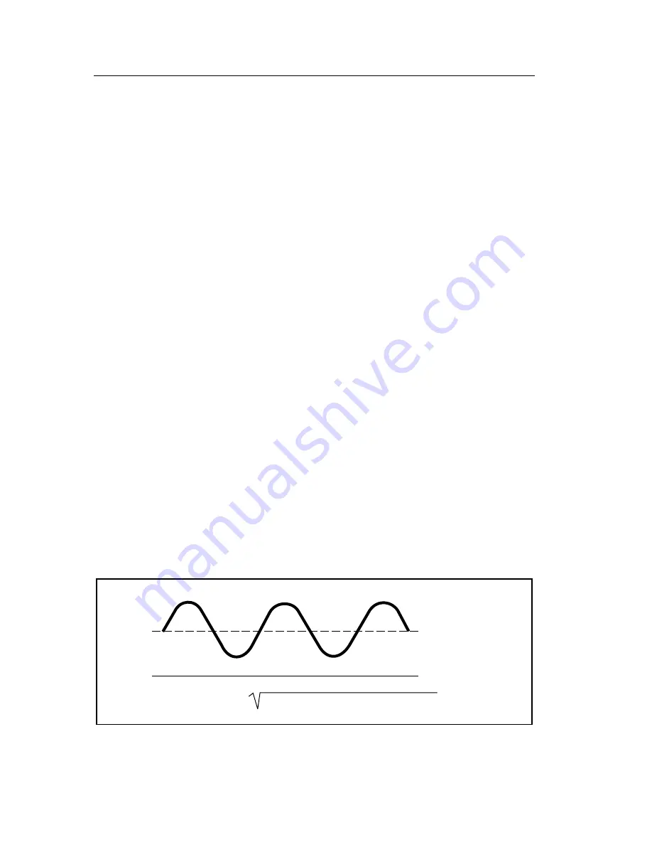
Remember, however, that when the 8062A measures signals with the ac
voltage function, the reading on the display does not include the dc
component (if it exists). For example, consider the waveform in Figure 2-7.
The ac voltage function will measure the ac rms component. The dc voltage
function will measure the dc component. To obtain the total rms value for
such a waveform, first measure the ac and dc values separately, then
calculate the total rms value using the formula given in Figure 2-7.
0V
(ac rms component)
2
+ (dc component)
2
RMS Total =
AC Component
DC Component
dy09f.eps
Figure 2-7. AC and DC Waveform Components
Summary of Contents for 8062A
Page 4: ......
Page 8: ...8062A Instruction Manual iv...
Page 10: ...8062A Instruction Manual vi...
Page 14: ...8062A Instruction Manual 1 2...
Page 24: ...8062A Instruction Manual 2 2...
Page 50: ...8062A Instruction Manual 2 28...
Page 52: ...8062A Instruction Manual 3 2...
Page 62: ...8062A Instruction Manual 3 12...
Page 64: ...8062A Instruction Manual 4 2...
Page 90: ...8062A Instruction Manual 4 28...
Page 92: ...8062A Instruction Manual 5 2...
Page 102: ...8062A Instruction Manual 5 12 8062A 4031 iv39c eps Figure 5 2 A1 Main PCB Assembly...
Page 106: ...8062A Instruction Manual 6 2...
Page 108: ...8062A Instruction Manual 6 4 dy55c eps Figure 6 1 Accessories...
Page 118: ...8062A Instruction Manual 7 2...
Page 122: ...8062A Instruction Manual 7 6...
Page 123: ...8062A Instruction Manual 7 7 8062A 1201 iu46c eps Figure 7 5 A1 Main PCB Schmatic Diagram...
Page 124: ...8062A Instruction Manual 7 8 8060A 1003 iu61f eps Figure 7 6 A3 RMS PCB Schmatic Diagram...


