


Introduction and Specifications
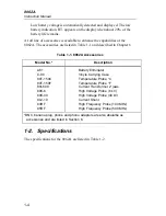
Specifications
1
1-7
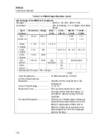
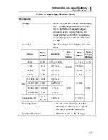
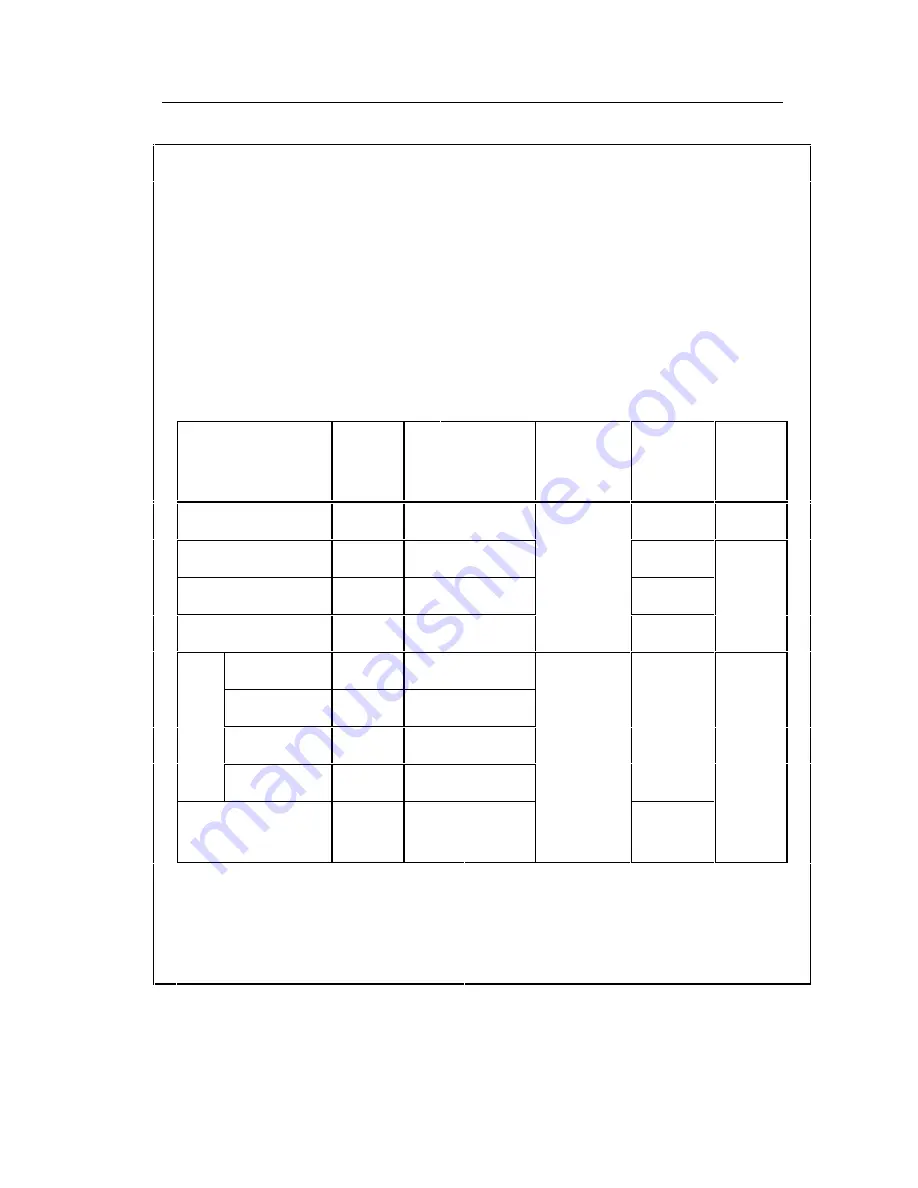
Table 1-2. 8062A Specifications (cont)
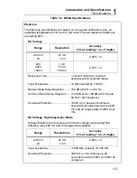
Resistance
Ranges...................................... 200
Ω
, 2 k
Ω
, 20 k
Ω
, 200 k
Ω
, autoranging
M
Ω
. The M
Ω
range extends from .0001
m
Ω
to 300 M
Ω
in three autoranged
ranges. Upscale range changes are
made at 2 M
Ω
and 20 M
Ω
. Downscale
range changes are made at 19 M
Ω
and
1.9 M
Ω
.
Accuracy ...................................
±
(% of r no. of digits). See table
below.
Range
Reso-
lution
Accuracy
Full-
scale
Voltage
Max
Current
Open
Circuit
Voltage
200
Ω
0.01
Ω
(0.1%+2+.02
Ω
)
<1.1 mA
<4.8V
2 k
Ω
0.1
Ω
(0.1%+2)
<250 mV
<150
µ
A
20 k
Ω
1
Ω
(0.1%+2)
<15
µ
A
<1.5V
200 k
Ω
10
Ω
(0.1%+2)
<1.5
µ
A
0-1.9999 M
Ω
100
Ω
(0.2%+2)
M
Ω
2-19.99 M
Ω
10 k
Ω
(0.25%+3)
<2.5
µ
A
20-99.9 M
Ω
100 k
Ω
(1%+3)
<2.5V
<2.5V
100-300 M
Ω
1 M
Ω
(2%+3)
Autoranging k
Ω
0.1
Ω
to 1 k
Ω
(.20%+5)
<1.0 mA
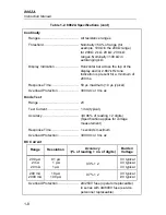
Response Time.............................. Two seconds maximum to rated
accuracy for all ranges except M
Ω
.
For M
Ω
, 8 seconds maximum.
Overload Protection ....................... 300V dc or rms ac for all ranges
Summary of Contents for 8062A
Page 4: ......
Page 8: ...8062A Instruction Manual iv...
Page 10: ...8062A Instruction Manual vi...
Page 14: ...8062A Instruction Manual 1 2...
Page 24: ...8062A Instruction Manual 2 2...
Page 50: ...8062A Instruction Manual 2 28...
Page 52: ...8062A Instruction Manual 3 2...
Page 62: ...8062A Instruction Manual 3 12...
Page 64: ...8062A Instruction Manual 4 2...
Page 90: ...8062A Instruction Manual 4 28...
Page 92: ...8062A Instruction Manual 5 2...
Page 102: ...8062A Instruction Manual 5 12 8062A 4031 iv39c eps Figure 5 2 A1 Main PCB Assembly...
Page 106: ...8062A Instruction Manual 6 2...
Page 108: ...8062A Instruction Manual 6 4 dy55c eps Figure 6 1 Accessories...
Page 118: ...8062A Instruction Manual 7 2...
Page 122: ...8062A Instruction Manual 7 6...
Page 123: ...8062A Instruction Manual 7 7 8062A 1201 iu46c eps Figure 7 5 A1 Main PCB Schmatic Diagram...
Page 124: ...8062A Instruction Manual 7 8 8060A 1003 iu61f eps Figure 7 6 A3 RMS PCB Schmatic Diagram...


