


8062A
Instruction Manual
1-8
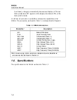
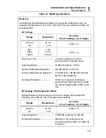
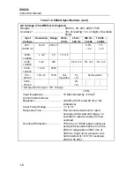
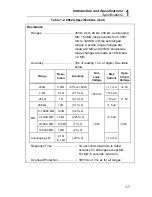
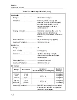
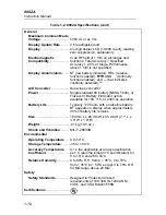
Table 1-2. 8062A Specifications (cont)
Continuity
Ranges........................................... All resistance ranges
Threshold ....................................... Nominally <50% of range (for
example, 100
Ω
in the 200
Ω
range)
for 200
Ω
, 2 k
Ω
, 20 k
Ω
, 200 k
Ω
ranges. Nominally <100 k
Ω
in
autoranging k
Ω
.
Display Indication........................... Horizontal bar across the top of the
display and/or 2.667 kHz tone.
Indication is present for a minimum of
200 ms.
Response Time.............................. 50
µ
s maximum (10
µ
s typical)
Overload Protection ....................... 300V dc or rms ac
Diode Test
Range ............................................ 2V
Test Current ................................... 1 mA (typical)
Accuracy ........................................
±
(0.06% of r 2 digits)
(Specification applies for voltage
measurement)
Response Time.............................. 1 seconds maximum
Overload Protection ....................... 300V dc or rms ac
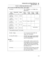
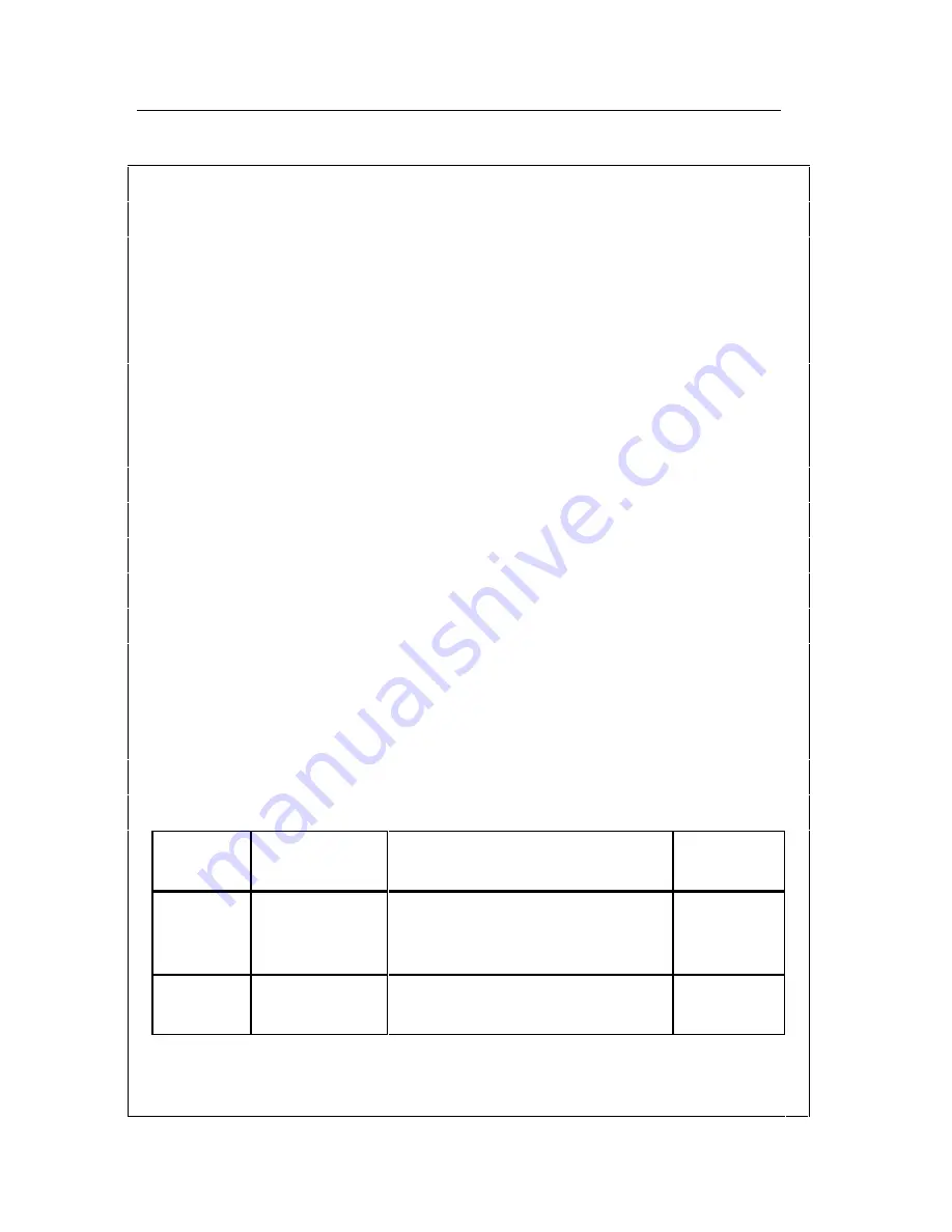
DC Current
Range
Resolution
Accuracy
±
(% of r no. of digits)
Burden
Voltage
200
µ
A
2 mA
20 mA
.01
µ
A
.1
µ
A
1
µ
A
0.3% + 2
.3V typical
.3V typical
.3V typical
200 mA
2000 mA
10
µ
A
100
µ
A
0.7% + 2
.3V typical
.9V typical
Overload Protection ....................... 2A/250V fuse (operator replaceable)
in series with 3A/600V fuse (service
personnel replaceable).
Summary of Contents for 8062A
Page 4: ......
Page 8: ...8062A Instruction Manual iv...
Page 10: ...8062A Instruction Manual vi...
Page 14: ...8062A Instruction Manual 1 2...
Page 24: ...8062A Instruction Manual 2 2...
Page 50: ...8062A Instruction Manual 2 28...
Page 52: ...8062A Instruction Manual 3 2...
Page 62: ...8062A Instruction Manual 3 12...
Page 64: ...8062A Instruction Manual 4 2...
Page 90: ...8062A Instruction Manual 4 28...
Page 92: ...8062A Instruction Manual 5 2...
Page 102: ...8062A Instruction Manual 5 12 8062A 4031 iv39c eps Figure 5 2 A1 Main PCB Assembly...
Page 106: ...8062A Instruction Manual 6 2...
Page 108: ...8062A Instruction Manual 6 4 dy55c eps Figure 6 1 Accessories...
Page 118: ...8062A Instruction Manual 7 2...
Page 122: ...8062A Instruction Manual 7 6...
Page 123: ...8062A Instruction Manual 7 7 8062A 1201 iu46c eps Figure 7 5 A1 Main PCB Schmatic Diagram...
Page 124: ...8062A Instruction Manual 7 8 8060A 1003 iu61f eps Figure 7 6 A3 RMS PCB Schmatic Diagram...


