


8062A
Instruction Manual
4-16
2.
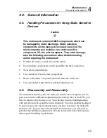
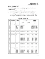
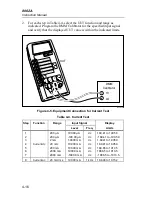
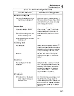
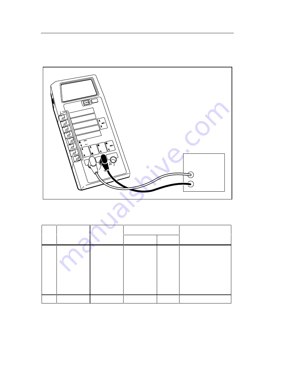
For each step in Table 4-4, select the UUT function and range as
indicated. Program the DMM Calibrator for the specified input signal
and verify that the displayed UUT value is within the indicated limits.
2000mA
A
A
COMMON
V
Ω
S
V
Ω
S
200mA
200
200k
200
µ
A
DC
AC
200mV
200
Ω
20mA
20
20k
2mA
2
2k
1000 DC
750 AC
M
Ω
REL
1000V DC
750V AC
MAX
2A MAX
500V MAX
!
!
DMM
Calibrator
HI
UUT
LO
dy36f.eps
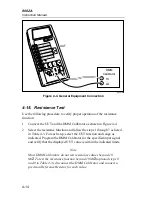
Figure 4-5. Equipment Connection for Current Test
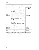
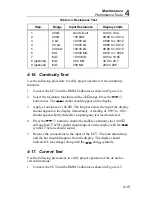
Table 4-4. Current Test
Step
Function
Range
Input Signal
Display
Level
Freq.
Limits
1
2
3
4
5
6
7
Current dc
200
µ
A
200
µ
A
2 mA
20 mA
200 mA
2000 mA
2000 mA
190.00
µ
A
-190.00
µ
A
1.9000 mA
19.000 mA
190.00 mA
1900.0 mA
-1900.0 mA
dc
dc
dc
dc
dc
dc
dc
189.41 to 190.59
-189.41 to -190.59
1.8941 to 1.9059
18.941 to 19.059
188.65 to 191.35
1886.5 to 1913.5
-1886.5 to -1913.5
8
Current ac
20 mA rms
19.000 mA
1 kHz
18.848 to 19.152
Summary of Contents for 8062A
Page 4: ......
Page 8: ...8062A Instruction Manual iv...
Page 10: ...8062A Instruction Manual vi...
Page 14: ...8062A Instruction Manual 1 2...
Page 24: ...8062A Instruction Manual 2 2...
Page 50: ...8062A Instruction Manual 2 28...
Page 52: ...8062A Instruction Manual 3 2...
Page 62: ...8062A Instruction Manual 3 12...
Page 64: ...8062A Instruction Manual 4 2...
Page 90: ...8062A Instruction Manual 4 28...
Page 92: ...8062A Instruction Manual 5 2...
Page 102: ...8062A Instruction Manual 5 12 8062A 4031 iv39c eps Figure 5 2 A1 Main PCB Assembly...
Page 106: ...8062A Instruction Manual 6 2...
Page 108: ...8062A Instruction Manual 6 4 dy55c eps Figure 6 1 Accessories...
Page 118: ...8062A Instruction Manual 7 2...
Page 122: ...8062A Instruction Manual 7 6...
Page 123: ...8062A Instruction Manual 7 7 8062A 1201 iu46c eps Figure 7 5 A1 Main PCB Schmatic Diagram...
Page 124: ...8062A Instruction Manual 7 8 8060A 1003 iu61f eps Figure 7 6 A3 RMS PCB Schmatic Diagram...


