


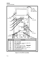


8062A
Instruction Manual
6-8
EXTENDED FREQUENCY
RESPONSE.......................................
Useful for relative readings from 20
kHz to 250 MHz
RESPONSE.......................................
Responds to the peak value of an
input and is calibrated to read rms
value of a sine wave.
VOLTAGE RANGE .........................
0.25 to 30V rms
MAXIMUM INPUT VOLTAGE......
30V rms, 200V dc
INPUT CAPACITANCE ..................
Approximately 3 pF
TEMPERATURE RANGE
Operating.........................................
Storage ............................................
+10
°
C to +35
°
C
-40
°
C to +75
°
C
HUMIDITY ......................................
<90% R.H.
OUTPUT CONNECTOR..................
Fits standard 0.75-inch dual banana
connectors
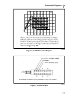
6-8. High Frequency Probe (85RF)
The Model 85RF High Frequency Probe allows measurements over a
frequency range of 100 kHz to 500 MHz from .25V to 30V rms. It operates
in conjunction with the instruments dc voltage ranges and provides a dc
output that is calibrated to be equivalent to the rms value of a sinewave input.
AC-to-DC RATIO.............................
1:1
RATIO ACCURACY (At 1 MHz
and loaded with 10 M
Ω
)
Above 0.5V .....................................
Below 0.5V .....................................
±
0.5 dB
±
1.0 dB
FREQUENCY RESPONSE
(Relative to 1 MHz)
100 kHz to 100 MHz.......................
*100 MHz to 200 MHz ...................
*200 MHz to 500 MHz ...................
*Referred to high and low inputs at
probe tip.
±
0.5 dB
±
1.0 dB
±
3.0 dB
EXTENDED FREQUENCY
RESPONSE.......................................
Useful for relative readings from 20
Summary of Contents for 8062A
Page 4: ......
Page 8: ...8062A Instruction Manual iv...
Page 10: ...8062A Instruction Manual vi...
Page 14: ...8062A Instruction Manual 1 2...
Page 24: ...8062A Instruction Manual 2 2...
Page 50: ...8062A Instruction Manual 2 28...
Page 52: ...8062A Instruction Manual 3 2...
Page 62: ...8062A Instruction Manual 3 12...
Page 64: ...8062A Instruction Manual 4 2...
Page 90: ...8062A Instruction Manual 4 28...
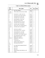
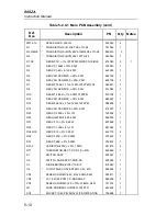
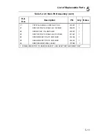
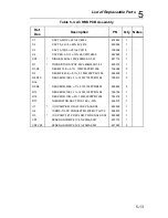
Page 92: ...8062A Instruction Manual 5 2...
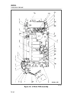
Page 102: ...8062A Instruction Manual 5 12 8062A 4031 iv39c eps Figure 5 2 A1 Main PCB Assembly...
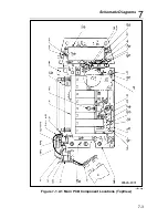
Page 106: ...8062A Instruction Manual 6 2...
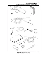
Page 108: ...8062A Instruction Manual 6 4 dy55c eps Figure 6 1 Accessories...
Page 118: ...8062A Instruction Manual 7 2...
Page 122: ...8062A Instruction Manual 7 6...
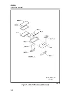
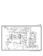
Page 123: ...8062A Instruction Manual 7 7 8062A 1201 iu46c eps Figure 7 5 A1 Main PCB Schmatic Diagram...
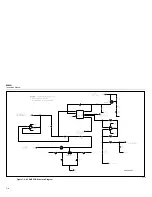
Page 124: ...8062A Instruction Manual 7 8 8060A 1003 iu61f eps Figure 7 6 A3 RMS PCB Schmatic Diagram...


