8062A
Instruction Manual
6-12
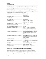
6-14. Slim Flex Test Lead Set (Y8140)
The Y8140 Test Lead Set consists of one red and one black 60-inch (1.52
meter) test lead, each with a standard banana plug on one end and an
extendable tip probe on the other end. This flexible metallic tip conductor
may be extended up to 2.5 inches and is insulated to within 0.1 inch of its tip.
This insulation reduces the chance of creating an inadvertent short circuit
while using the probes in their extended configuration. Intended primarily for
measuring voltages, the Y8140 leads may also be used for measuring modest
currents.
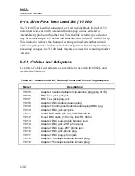
6-15. Cables and Adapters
A variety of cables and adapters are available for use with the 8062A, and
are listed in Table 6-1.
Table 6-1. Cables and BNC, Banana, Phone and Phono Plug Adapters
Model
Description
Y9105
Y9106
Y9107
Y9108
Y9109
Y9110
Y9111
Y9112
Y9113
Y9114
Y9115
Y9116
Y9117
Y9118
Y9119
Adapter: Insulated alligator clip-banana plug (pkg. of 10)
BNC Tee, jack-jack-jack
BNC Tee, jack-plug-jack
Adapter: BNC-double banana plug
Adapter: Binding post/double banana plug-BNC plug
Adapter: BNC jack-pcb pins
3-foot BNC cable (97 cm), 50
Ω
RG 58C/U
6-foot BNC cable (1.95 cm), 50
Ω
RG 58C/U
Adapter: BNC plug-double banana plug
Adapter: BNC jack-.250” phone plug
Adapter: BNC plug-.250” phone jack
Adapter: BNC jack-phono plug
Adapter: BNC plug-phono jack
Adapter: Phone jack-double banana plug
Adapter: Phono jack-double banana plug
Summary of Contents for 8062A
Page 4: ......
Page 8: ...8062A Instruction Manual iv...
Page 10: ...8062A Instruction Manual vi...
Page 14: ...8062A Instruction Manual 1 2...
Page 24: ...8062A Instruction Manual 2 2...
Page 50: ...8062A Instruction Manual 2 28...
Page 52: ...8062A Instruction Manual 3 2...
Page 62: ...8062A Instruction Manual 3 12...
Page 64: ...8062A Instruction Manual 4 2...
Page 90: ...8062A Instruction Manual 4 28...
Page 92: ...8062A Instruction Manual 5 2...
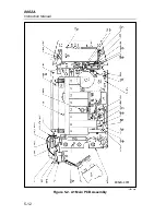
Page 102: ...8062A Instruction Manual 5 12 8062A 4031 iv39c eps Figure 5 2 A1 Main PCB Assembly...
Page 106: ...8062A Instruction Manual 6 2...
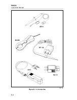
Page 108: ...8062A Instruction Manual 6 4 dy55c eps Figure 6 1 Accessories...
Page 118: ...8062A Instruction Manual 7 2...
Page 122: ...8062A Instruction Manual 7 6...
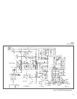
Page 123: ...8062A Instruction Manual 7 7 8062A 1201 iu46c eps Figure 7 5 A1 Main PCB Schmatic Diagram...
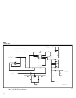
Page 124: ...8062A Instruction Manual 7 8 8060A 1003 iu61f eps Figure 7 6 A3 RMS PCB Schmatic Diagram...

