Maintenance
Troubleshooting
4
4-25
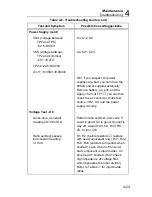
Table 4-6. Troubleshooting Guide (cont)
Test and Symptom
Possible Cause/Suggestions
Resistance Test (cont)
Low range readings correct,
high range readings off
Q3 and Q4 leak-check by seeing if
M
Ω
reads OL with open input. Main
pcb contaminated - clean carefully
and check performance.
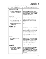
Current Test
Constant reading of 0.00
Check fuses F1 and F2 with fuse
check procedure in Chapter 2-4.
Fuses F1 and F2 good, but
current readings off
Switches and resistors in current
shunt.
High crest-factor ac current
readings off
U1
Continuity Test
No response
Select switch decoding self-test
check for proper function decoding
and also confirm that the continuity
comparator responds. R31, S1A
No tone
Q6, R4, LS1. Check U3-1 (tone
output) with scope for 2.667 kHz
signal.
Diode Test
No readings or very low
readings
CR1 (diode test source). To check
CR1, select diode test, connect an
external 1 k
Ω
resistor across the
inputs and measure the voltage
across the resistor
should be
approximately 1V (
±
10%).
BT Indicator
BT indicator not displayed
when battery voltage is
less that 5.6V
U3, Z4-U3 compares voltage at pin
18 (BT1) with voltage at pin 10
(COM-analog common voltage). BT
turns on if U3-18 voltage is greater
than common. turns off if it is less
(
±
50 mV)
Summary of Contents for 8062A
Page 4: ......
Page 8: ...8062A Instruction Manual iv...
Page 10: ...8062A Instruction Manual vi...
Page 14: ...8062A Instruction Manual 1 2...
Page 24: ...8062A Instruction Manual 2 2...
Page 50: ...8062A Instruction Manual 2 28...
Page 52: ...8062A Instruction Manual 3 2...
Page 62: ...8062A Instruction Manual 3 12...
Page 64: ...8062A Instruction Manual 4 2...
Page 90: ...8062A Instruction Manual 4 28...
Page 92: ...8062A Instruction Manual 5 2...
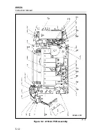
Page 102: ...8062A Instruction Manual 5 12 8062A 4031 iv39c eps Figure 5 2 A1 Main PCB Assembly...
Page 106: ...8062A Instruction Manual 6 2...
Page 108: ...8062A Instruction Manual 6 4 dy55c eps Figure 6 1 Accessories...
Page 118: ...8062A Instruction Manual 7 2...
Page 122: ...8062A Instruction Manual 7 6...
Page 123: ...8062A Instruction Manual 7 7 8062A 1201 iu46c eps Figure 7 5 A1 Main PCB Schmatic Diagram...
Page 124: ...8062A Instruction Manual 7 8 8060A 1003 iu61f eps Figure 7 6 A3 RMS PCB Schmatic Diagram...

