


8062A
Instruction Manual
1-4
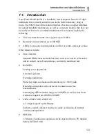
Low battery voltage is automatically detected and displayed. The low
battery indication, BT, appears on the display when about 20% of the
battery life remains.
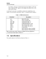
A full line of accessories is available to enhance the capabilities of the
8062A. The accessories are listed in Table 1-1 and described in Chapter 6.
Table 1-1. 8062A Accessories
Model No.*
Description
A81
C-90
80T-150C
80T-150F
80I-600
80K-6
80K-40
80J-10
83RF
85RF
Battery Eliminator
Vinyle Carrying Case
Temperature Probe °C
Temperature Probe °F
Current Transformer 2’ jaws
High Voltage Probe (6 kV)
High Voltage Probe (40 kV)
Current Shunt
High Frequency Probe (100 MHz)
High Frequency Probe (500 MHz)
*BNC, banana plug, phone and phono adapters are also abaialbe as
accessories and are listed in Section 6.
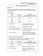
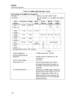
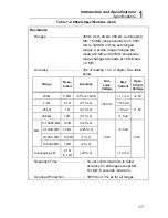
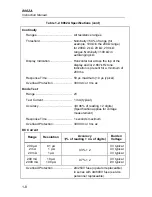
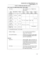
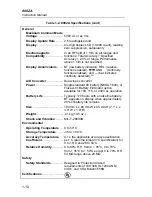
1-2. Specifications
The specifications for the 8062A are listed in Table 1-2.
Summary of Contents for 8062A
Page 4: ......
Page 8: ...8062A Instruction Manual iv...
Page 10: ...8062A Instruction Manual vi...
Page 14: ...8062A Instruction Manual 1 2...
Page 24: ...8062A Instruction Manual 2 2...
Page 50: ...8062A Instruction Manual 2 28...
Page 52: ...8062A Instruction Manual 3 2...
Page 62: ...8062A Instruction Manual 3 12...
Page 64: ...8062A Instruction Manual 4 2...
Page 90: ...8062A Instruction Manual 4 28...
Page 92: ...8062A Instruction Manual 5 2...
Page 102: ...8062A Instruction Manual 5 12 8062A 4031 iv39c eps Figure 5 2 A1 Main PCB Assembly...
Page 106: ...8062A Instruction Manual 6 2...
Page 108: ...8062A Instruction Manual 6 4 dy55c eps Figure 6 1 Accessories...
Page 118: ...8062A Instruction Manual 7 2...
Page 122: ...8062A Instruction Manual 7 6...
Page 123: ...8062A Instruction Manual 7 7 8062A 1201 iu46c eps Figure 7 5 A1 Main PCB Schmatic Diagram...
Page 124: ...8062A Instruction Manual 7 8 8060A 1003 iu61f eps Figure 7 6 A3 RMS PCB Schmatic Diagram...