


Maintenance
Calibration Adjustments
4
4-17
4-18. Diode Test
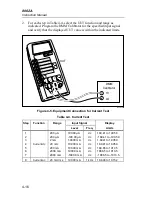
Use the following procedure to verify proper operation of the diode test:
1.
Remove any connections to the inputs of the UUT and select the diode
test function. The display should indicate OL (overrange).
2.
Connect the UUT and the DMM Calibrator as shown in Figure 4-4 and
apply a resistance of 1.000 k
Ω
. A reading of .9000 to 1.1000 (typical)
should appear on the UUT display.
4-19. Calibration Adjustments
Under normal operating conditions the 8062A should maintain the
specifications given in Chapter 1 of this manual for at least one year after
calibration. If your 8062A has been repaired or if it has failed any of the
performance tests, you need to perform the calibration adjustments.
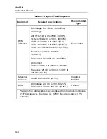
Test equipment needed for the adjustments are listed in Table 4-1. If the test
equipment is not available, your nearest Fluke Service Center will be glad to
help. Call (toll-free) 800-426-0361 for assistance. After you have completed
the calibration adjustments, we recommend that you complete the
performance tests to verify proper operation. In the following procedure, the
8062A that is being adjusted is referred to as the UUT (Unit Under Test).
Note
The top ac shield should remain installed in the instrument while
the calibration adjustments are being performed. The positions of
the trimpots and trimcaps are marked on the top ac shield along
with a table summarizing the calibration procedures.
Note
The performance of the 8062A ac functions is affected by the
capacitance between the main pcb and the bottom ac shield, which
is dependent on the distance between them. The distance may vary,
depending on whether the top cover is installed. To minimize
performance variations, make certain the intstrument is firmly
seated in the bottom case before making any calibration
adjustments. After you have performed the adjustments and
installed the top cover, if you find that the measurement values
obtained for the ac function performance tests are consistently too
high or too low, remove the top cover and repeat the adjustments
accordingly.
Summary of Contents for 8062A
Page 4: ......
Page 8: ...8062A Instruction Manual iv...
Page 10: ...8062A Instruction Manual vi...
Page 14: ...8062A Instruction Manual 1 2...
Page 24: ...8062A Instruction Manual 2 2...
Page 50: ...8062A Instruction Manual 2 28...
Page 52: ...8062A Instruction Manual 3 2...
Page 62: ...8062A Instruction Manual 3 12...
Page 64: ...8062A Instruction Manual 4 2...
Page 90: ...8062A Instruction Manual 4 28...
Page 92: ...8062A Instruction Manual 5 2...
Page 102: ...8062A Instruction Manual 5 12 8062A 4031 iv39c eps Figure 5 2 A1 Main PCB Assembly...
Page 106: ...8062A Instruction Manual 6 2...
Page 108: ...8062A Instruction Manual 6 4 dy55c eps Figure 6 1 Accessories...
Page 118: ...8062A Instruction Manual 7 2...
Page 122: ...8062A Instruction Manual 7 6...
Page 123: ...8062A Instruction Manual 7 7 8062A 1201 iu46c eps Figure 7 5 A1 Main PCB Schmatic Diagram...
Page 124: ...8062A Instruction Manual 7 8 8060A 1003 iu61f eps Figure 7 6 A3 RMS PCB Schmatic Diagram...


