


8062A
Instruction Manual
4-22
•
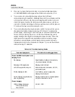
One way to check the input circuitry is to attach a high impedance
(>1000 M
Ω
) DMM at the input of the 8062A a/d converter, U3-6.
•
You can do a lot of troubleshooting without the LCD and
microcomputer pcb installed. Although there will be no display and the
a/d converter will not work, the power supplies still work so you can
check the input circuitry, the diode test and ohms sources, and the ac
converter. Another advantage is that you gain access to all the pins on
U3 without having to turn the main pcb over.
•
You can troubleshoot the input circuitry with U3 removed (be sure to
disconnect the battery before removing U3). Since U3 controls the
power supply, removing U3 will cause the ac converter and diode test
source to stop working. However, it will also eliminate any power
supply leakages that might be affecting the input circuitry. Since the
input protection, input divider and ohms reference resistors, amps
protection, current shunts, and a/d input circuits consist of passive
components (refer to the schematic in Chapter 7) you can check them
without having U3 installed.
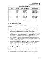
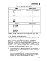
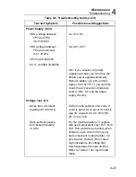
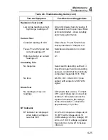
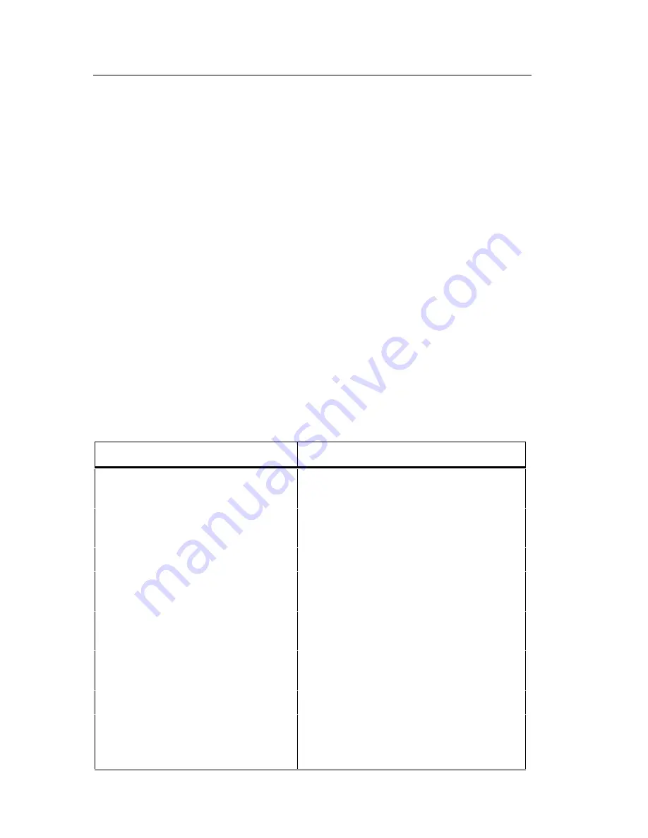
Table 4-6. Troubleshooting Guide
Test and Symptom
Possible Cause/Suggestions
Power On/Microcomputer and
Display Test
No display
Dead battery, battery connections,
J4, power supply circuitry.
Missing LCD segments
Display interconnect.
All LCD segments stay on
Microcomputer connector, U5, U3,
pcb lands open.
Entire display is dim
Low battery, power supply low,
display interconnect.
Some display segments are
dim or ghosting
Display interconnect, contamination
on pcb connector or LCD.
Power Supply
VDD (voltage between
TP7 and common)
≠
5.2
±
0.12V
U3, Q1, VR1
Summary of Contents for 8062A
Page 4: ......
Page 8: ...8062A Instruction Manual iv...
Page 10: ...8062A Instruction Manual vi...
Page 14: ...8062A Instruction Manual 1 2...
Page 24: ...8062A Instruction Manual 2 2...
Page 50: ...8062A Instruction Manual 2 28...
Page 52: ...8062A Instruction Manual 3 2...
Page 62: ...8062A Instruction Manual 3 12...
Page 64: ...8062A Instruction Manual 4 2...
Page 90: ...8062A Instruction Manual 4 28...
Page 92: ...8062A Instruction Manual 5 2...
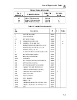
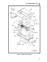
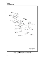
Page 102: ...8062A Instruction Manual 5 12 8062A 4031 iv39c eps Figure 5 2 A1 Main PCB Assembly...
Page 106: ...8062A Instruction Manual 6 2...
Page 108: ...8062A Instruction Manual 6 4 dy55c eps Figure 6 1 Accessories...
Page 118: ...8062A Instruction Manual 7 2...
Page 122: ...8062A Instruction Manual 7 6...
Page 123: ...8062A Instruction Manual 7 7 8062A 1201 iu46c eps Figure 7 5 A1 Main PCB Schmatic Diagram...
Page 124: ...8062A Instruction Manual 7 8 8060A 1003 iu61f eps Figure 7 6 A3 RMS PCB Schmatic Diagram...


