Operation Instructions
Initial Check-Out Procedure
2
2-25
2-22. Continuity (
)
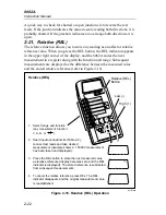
To select the continuity function, first select the resistance function and then
press the
button under the display. The
button functions like
a three-position switch: the first button press enables visible continuity (the
indicator is displayed), the second button press enables audible
continuity (the
is displayed), and the third button press cancels
continuity selection (the
indicator disappears). The selection of
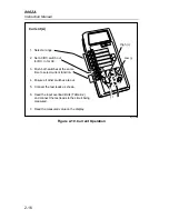
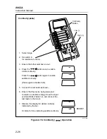
continuity is summarized in Figure 2-16. When continuity is detected, visible
continuity is indicated by the long bar across the top of the display. Audible
continuity (if enabled) is indicated by the tone emitted from the instrument.
Continuity is a quick check to verify whether circuit connections are intact.
The continuity detection threshold is typically <50% of the resistance range
selected for the fixed ranges (i.e. continuity is detected if resistance is less
than 100
Ω
in the 200
Ω
range, less than 1 k
Ω
in the 2 k
Ω
range, etc.). The
detection threshold is <100
Ω
for the autoranging k
Ω
range, and <100 M
Ω
for the autoranging M
Ω
range.
The 8062A can detect continuity for intervals as brief as 50
µ
s (typically as
brief as 10
µ
s). It extends the visible of audible indication to a minimum of
200 ms to make it easy to observe results. Note that while continuity is
enabled, the 8062A still makes resistance measurements and displays the
readings.
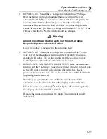
2-23. Initial Check-Out Procedure
Here is an easy procedure you can use to verify that your 8062A is operating
properly for most functions. All you need to perform these tests are the test
leads and access to a standard wall socket. Remember that you are not trying
to verify the instrument accuracy, but are simply confirming that the
functions work. Performance tests and calibration adjustments are presented
in Chapter 4. If the instrument passes the self-test when the instrument is first
turned on, then the display and the microcomputer are working properly.
Summary of Contents for 8062A
Page 4: ......
Page 8: ...8062A Instruction Manual iv...
Page 10: ...8062A Instruction Manual vi...
Page 14: ...8062A Instruction Manual 1 2...
Page 24: ...8062A Instruction Manual 2 2...
Page 50: ...8062A Instruction Manual 2 28...
Page 52: ...8062A Instruction Manual 3 2...
Page 62: ...8062A Instruction Manual 3 12...
Page 64: ...8062A Instruction Manual 4 2...
Page 90: ...8062A Instruction Manual 4 28...
Page 92: ...8062A Instruction Manual 5 2...
Page 102: ...8062A Instruction Manual 5 12 8062A 4031 iv39c eps Figure 5 2 A1 Main PCB Assembly...
Page 106: ...8062A Instruction Manual 6 2...
Page 108: ...8062A Instruction Manual 6 4 dy55c eps Figure 6 1 Accessories...
Page 118: ...8062A Instruction Manual 7 2...
Page 122: ...8062A Instruction Manual 7 6...
Page 123: ...8062A Instruction Manual 7 7 8062A 1201 iu46c eps Figure 7 5 A1 Main PCB Schmatic Diagram...
Page 124: ...8062A Instruction Manual 7 8 8060A 1003 iu61f eps Figure 7 6 A3 RMS PCB Schmatic Diagram...

