

8062A
Instruction Manual
2-22
A quick way to check for shorted or open junctions is to reverse the test
leads. If the junction indicates the same in-scale reading both directions, it is
probably shorted. If the junction indicates an overrange both directions, it is
open.
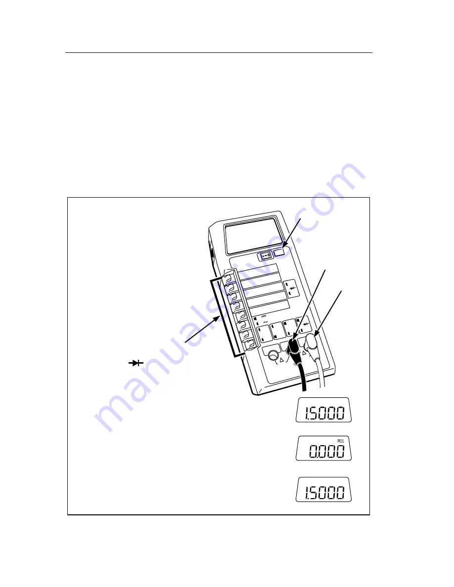
2-21. Relative (REL)
The relative function allows you to store any reading as an offset or relative
reference value. When you press the REL button, the REL indicator appears
in the upper right corner of the display, and the 8062A stores the next
measurement in a register along with the function and range. Subsequent
measurements are displayed as the difference between the measured value
and the stored relative reference (refer to Figure 2-15).
2000mA
A
A
COMMON
V
Ω
S
V
Ω
S
200mA
200
200k
200
µ
A
DC
AC
200mV
200
Ω
20mA
20
20k
2mA
2
2k
1000 DC
750 AC
M
Ω
REL
1000V DC
750V AC
MAX
2A MAX
500V MAX
!
!
Relative (REL)
Relative (REL)
Button
Low (-)
High (+)
1. Select range and function
(any measurement function:
V, A,
Ω
, or ).
2. Heed input overload limits (Table 2-2),
connect test leads and take desired
measurement (example shows a 1.5000V measurement
has been taken and displayed):
3. Press the REL button to store the next measured value
as relative reference (display becomes zero and the REL
indicator is displayed). The stored reference is subtracted
from subsequent measurements:
4. To cancel the relative reference, press REL. The REL
indicator disappears and the original measurement value
is reestablished:
dy18f.eps
Figure 2-15. Relative (REL) Operation
Summary of Contents for 8062A
Page 4: ......
Page 8: ...8062A Instruction Manual iv...
Page 10: ...8062A Instruction Manual vi...
Page 14: ...8062A Instruction Manual 1 2...
Page 24: ...8062A Instruction Manual 2 2...
Page 50: ...8062A Instruction Manual 2 28...
Page 52: ...8062A Instruction Manual 3 2...
Page 62: ...8062A Instruction Manual 3 12...
Page 64: ...8062A Instruction Manual 4 2...
Page 90: ...8062A Instruction Manual 4 28...
Page 92: ...8062A Instruction Manual 5 2...
Page 102: ...8062A Instruction Manual 5 12 8062A 4031 iv39c eps Figure 5 2 A1 Main PCB Assembly...
Page 106: ...8062A Instruction Manual 6 2...
Page 108: ...8062A Instruction Manual 6 4 dy55c eps Figure 6 1 Accessories...
Page 118: ...8062A Instruction Manual 7 2...
Page 122: ...8062A Instruction Manual 7 6...
Page 123: ...8062A Instruction Manual 7 7 8062A 1201 iu46c eps Figure 7 5 A1 Main PCB Schmatic Diagram...
Page 124: ...8062A Instruction Manual 7 8 8060A 1003 iu61f eps Figure 7 6 A3 RMS PCB Schmatic Diagram...