


Operation Instructions
Operation
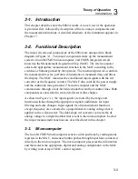
2
2-21
2-20. Diode Test (
G
)
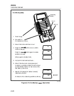
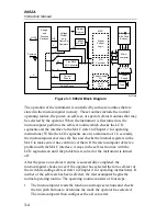
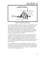
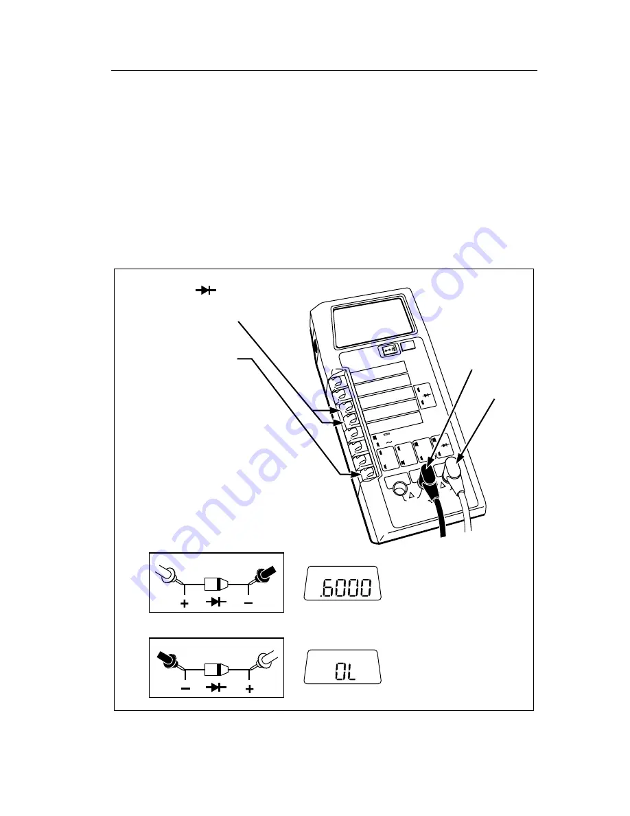
Selection of the diode test is described in Figure 2-14. Notice how the test
leads are placed to forward-bias or reverse-bias the diode in the figure.
The diode test measures the forward voltage of a semiconductor junction (or
junctions) at a 1 mA (
±
10%) test current. Readings are displayed in the 2V
range, with OL displayed for voltages greater than 2V. For a silicon diode,
the typical forward voltage at 1 mA is about 0.6V. A reverse-biased
semiconductor junction should display the overrange (OL) indicator
provided that any resistance parallel to the junction is greater than 2 k
Ω
.
2000mA
A
A
COMMON
V
Ω
S
V
Ω
S
200mA
200
200k
200
µ
A
DC
AC
200mV
200
Ω
20mA
20
20k
2mA
2
2k
1000 DC
750 AC
M
Ω
REL
1000V DC
750V AC
MAX
2A MAX
500V MAX
!
!
Diode Test ( )
Low (-)
Forward Bias:
High (+)
Typical r
forward-biased
silicon diode.
Overrange display
if parallel resistance
is >2 K
Ω
.
Reverse Bias:
Black
Red
Black
Red
1. Press both switches
simultaneously
2. Set switch to select
diode test
3. Ensure all other switches
are out (except the AC/DC
switch which can be in or out).
4. Connect the test leads as shown.
5. Heed the input overload limits
(Table 2-2) and connect the test
leads to diode being measured.
6. Read the measured value on the display.
dy17f.eps
Figure 2-14. Diode Test
Summary of Contents for 8062A
Page 4: ......
Page 8: ...8062A Instruction Manual iv...
Page 10: ...8062A Instruction Manual vi...
Page 14: ...8062A Instruction Manual 1 2...
Page 24: ...8062A Instruction Manual 2 2...
Page 50: ...8062A Instruction Manual 2 28...
Page 52: ...8062A Instruction Manual 3 2...
Page 62: ...8062A Instruction Manual 3 12...
Page 64: ...8062A Instruction Manual 4 2...
Page 90: ...8062A Instruction Manual 4 28...
Page 92: ...8062A Instruction Manual 5 2...
Page 102: ...8062A Instruction Manual 5 12 8062A 4031 iv39c eps Figure 5 2 A1 Main PCB Assembly...
Page 106: ...8062A Instruction Manual 6 2...
Page 108: ...8062A Instruction Manual 6 4 dy55c eps Figure 6 1 Accessories...
Page 118: ...8062A Instruction Manual 7 2...
Page 122: ...8062A Instruction Manual 7 6...
Page 123: ...8062A Instruction Manual 7 7 8062A 1201 iu46c eps Figure 7 5 A1 Main PCB Schmatic Diagram...
Page 124: ...8062A Instruction Manual 7 8 8060A 1003 iu61f eps Figure 7 6 A3 RMS PCB Schmatic Diagram...


