


Maintenance
Troubleshooting
4
4-21
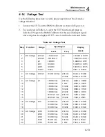
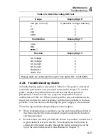
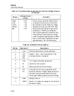
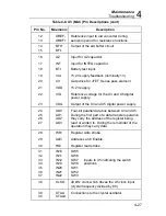
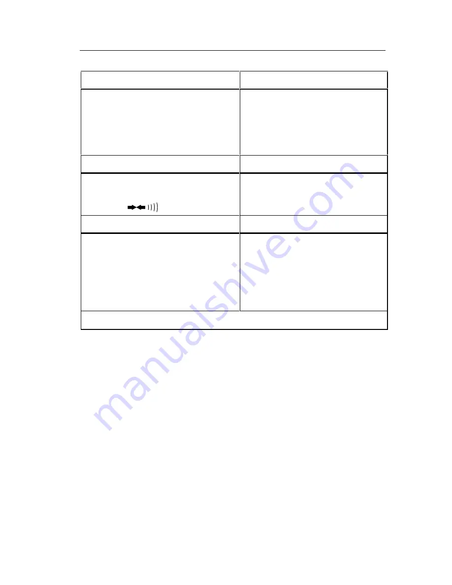
Table 4-5. Switch Decoding Self-Test
Range
Display Digit 0*
200 (
µ
A, mV or
Ω
)
2
20
200
2000
0 (default if no range selected)
1
2
3
4
Push Button
Display Digit 1*
none
REL
0
1
2
Function
Display Digit 3*
AC Voltage
DC Voltage
AC Current
DC Current
Resistance
Diode Test
1
2
3
4
5
7
*Display digits are numbered 0 through 4 from right (LSD ) to left (MSD).
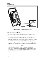
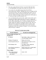
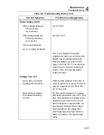
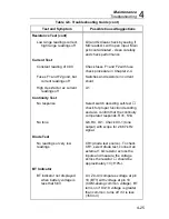
4-24. Troubleshooting Guide
A troubleshooting guide is presented in Table 4-6. The guide is structured
around the performance tests presented earlier in this chapter. To use this
guide, complete the performance tests and note any discrepancies in
performance. Then locate the test, symptom, and possible cause of
malfunction in Table 4-6. When several possible causes of malfunction are
listed, they are listed in order beginning with the most probable to the least
probable. A section abut troubleshooting the power supply is also included.
The following troubleshooting techniques can be helpful:
•
When troubleshooting, remember to use the switch decoding self-test to
determine whether the microcomputer properly interprets the function
and range selection.
•
Do not remove the main pcb from the bottom case unless you must do so
to gain electrical access to circuits. You can gain electrical access to
almost all of the input circuitry through the switch contact pins on the
top of the switch deck (refer to the schematic in Chapter 7).
Summary of Contents for 8062A
Page 4: ......
Page 8: ...8062A Instruction Manual iv...
Page 10: ...8062A Instruction Manual vi...
Page 14: ...8062A Instruction Manual 1 2...
Page 24: ...8062A Instruction Manual 2 2...
Page 50: ...8062A Instruction Manual 2 28...
Page 52: ...8062A Instruction Manual 3 2...
Page 62: ...8062A Instruction Manual 3 12...
Page 64: ...8062A Instruction Manual 4 2...
Page 90: ...8062A Instruction Manual 4 28...
Page 92: ...8062A Instruction Manual 5 2...
Page 102: ...8062A Instruction Manual 5 12 8062A 4031 iv39c eps Figure 5 2 A1 Main PCB Assembly...
Page 106: ...8062A Instruction Manual 6 2...
Page 108: ...8062A Instruction Manual 6 4 dy55c eps Figure 6 1 Accessories...
Page 118: ...8062A Instruction Manual 7 2...
Page 122: ...8062A Instruction Manual 7 6...
Page 123: ...8062A Instruction Manual 7 7 8062A 1201 iu46c eps Figure 7 5 A1 Main PCB Schmatic Diagram...
Page 124: ...8062A Instruction Manual 7 8 8060A 1003 iu61f eps Figure 7 6 A3 RMS PCB Schmatic Diagram...