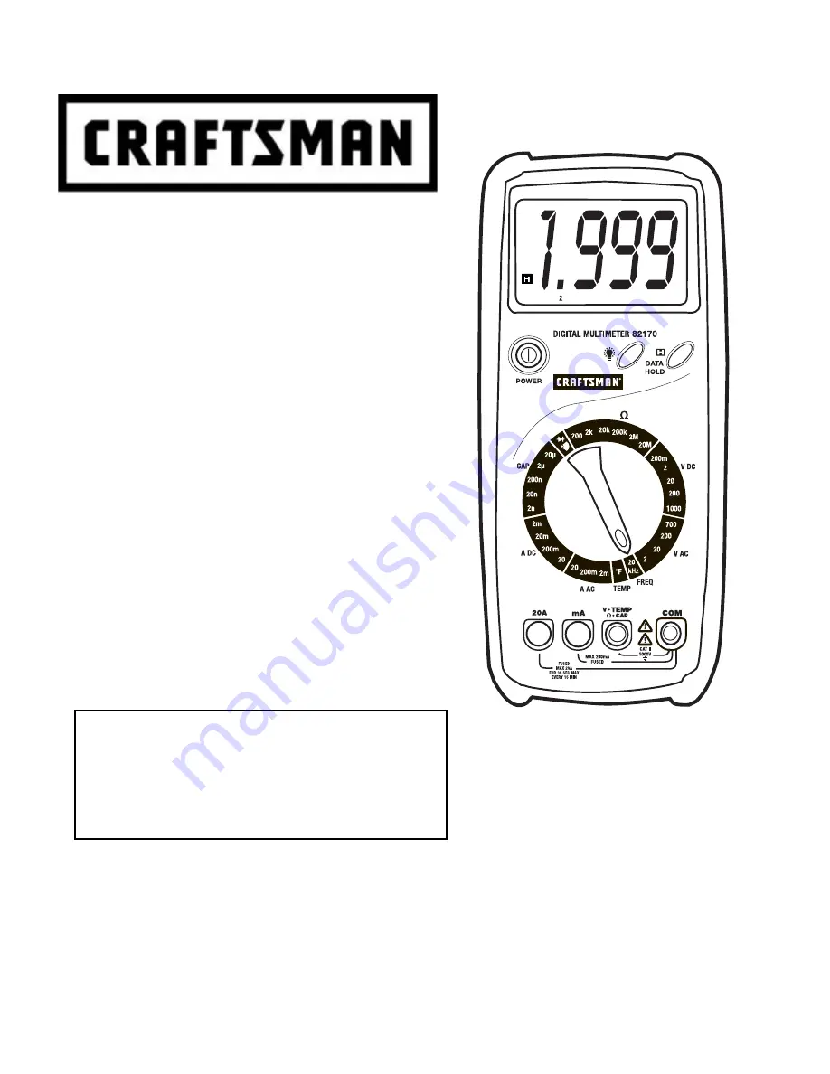
background image

Owner's Manual 


Digital MultiMeter 


Model No.


82170


Sears, Roebuck and Co., Hoffman Estates, IL 60179 

www.craftsman.com 061606 

 Safety 

 Operation 

 Maintenance 

 Español 

CAUTION

: Read, understand and 

follow Safety Rules and Operating 
Instructions in this manual before 
using this product. 

Summary of Contents for 82170

Page 1: ...odel No 82170 Sears Roebuck and Co Hoffman Estates IL 60179 www craftsman com 061606 Safety Operation Maintenance Español CAUTION Read understand and follow Safety Rules and Operating Instructions in this manual before using this product ...

Page 2: ... 9 Backlight 9 Range Indicator 9 Safety Shutters 9 DC Voltage Measurements 10 AC Voltage Measurements 10 DC Current Measurements 11 AC Current Measurements 11 Resistance Measurements 12 Continuity Check 12 Diode Test 13 Frequency Measurements 13 Capacitance Measurements 14 Temperature Measurements 14 Maintenance 15 Replacing Batteries 15 Replacing Fuses 16 Troubleshooting 17 Service and Parts 17 ...

Page 3: ...ses this warranty applies for 90 days from the date of purchase This warranty gives you specific legal rights and you may also have other rights which vary from state to state Sears Roebuck and Co Dept 817WA Hoffman Estates IL 60179 For Customer Assistance Call 9am 5 PM EST Monday through Friday 1 888 326 1006 WARNING USE EXTREME CAUTION IN THE USE OF THIS DEVICE Improper use of this device can re...

Page 4: ...inuity Temperature 250V DC AC 2 USE EXTREME CAUTION when working with high voltages 3 DO NOT measure voltage if the voltage on the COM input jack exceeds 500V above earth ground 4 NEVER connect the meter leads across a voltage source while the function switch is in the current resistance or diode mode Doing so can damage the meter 5 ALWAYS discharge filter capacitors in power supplies and disconne...

Page 5: ...t be connected to a circuit point at which the voltage with respect to earth ground exceeds in this case 500 VAC or VDC This symbol adjacent to one or more terminals identifies them as being associated with ranges that may in normal use be subjected to particularly hazardous voltages For maximum safety the meter and its test leads should not be handled when these terminals are energized Double Ins...

Page 6: ...0 8 reading 3 digits 2V 1mV 20V 10mV 200V 100mV 1 0 reading 5 digits AC Voltage V AC 40 400Hz 700V 1V 1 2 reading 5 digits 2mA 1µA 20mA 10µA 1 0 reading 3 digits 200mA 100µA 1 5 reading 5 digits DC Current A DC 20A 10mA 2 0 reading 10 digits 2mA 1µA 1 2 reading 5 digits 200mA 100µA 2 0 reading 5 digits AC Current A AC 40 400Hz 20A 10mA 3 0 reading 10 digits 200Ω 0 1Ω 1 0 reading 10 digits 2kΩ 1Ω 2...

Page 7: ...igital converter NOTE Accuracy is stated at 64 o F to 82 o F 18 o C to 28 o C and less than 75 RH ambient MultiMeter conditions Diode Test Test current of approximately 1mA open circuit voltage 2 8V DC typical Continuity Check Audible signal will sound if the resistance is less than approximately 40Ω open circuit voltage 2 8V DC typical Temperature sensor Type K temperature probe Input Impedance 1...

Page 8: ...nt etc with transient overvoltages less than Overvoltage Category III BATTERY INSTALLATION WARNING To avoid electric shock disconnect the test leads from any source of voltage before removing the battery door 1 Disconnect the test leads from the meter 2 Open the battery door by lifting the rear stand and removing the two screws using a Phillips head screwdriver 3 Insert the battery into battery ho...

Page 9: ...ed to a circuit DATA HOLD The Data Hold function allows the meter to freeze a measurement for later reference 1 Press the DATA HOLD button to freeze the reading on the indicator The indicator H will be appear in the display 2 Press the DATA HOLD button to return to normal operation BACKLIGHT The backlight function illuminates the display to improve readability in dimly lighted areas 1 Press the bu...

Page 10: ...The probe tips may not be long enough to contact the live parts inside some 240V outlets for appliances because the contacts are recessed deep in the outlets As a result the reading may show 0 volts when the outlet actually has voltage on it Make sure the probe tips are touching the metal contacts inside the outlet before assuming that no voltage is present CAUTION Do not measure AC voltages if a ...

Page 11: ...test probe tip to the positive side of the circuit 6 Apply power to the circuit 7 Read the current in the display For mA DC measurements reset the function switch to successively lower mA DC positions to obtain a higher resolution reading The display will indicate the proper decimal point and value AC CURRENT MEASUREMENTS WARNING To avoid electric shock do not measure AC current on any circuit who...

Page 12: ...ana plug into the negative COM jack Insert the red test lead banana plug into the positive Ω jack 3 Touch the test probe tips across the circuit or part under test It is best to disconnect one side of the part under test so the rest of the circuit will not interfere with the resistance reading 4 Read the resistance in the display and then set the function switch to the lowest Ω position that is gr...

Page 13: ... reading shows a value and the other reading shows 1 the diode is good B If both readings show 1 the device is open C If both readings are very small or 0 the device is shorted NOTE The value indicated in the display during the diode check is the forward voltage FREQUENCY MEASUREMENT 1 Set the function switch to the FREQ position 2 Insert the black test lead banana plug into the negative COM jack ...

Page 14: ...ated capacitance The display will indicate the proper decimal point and value TEMPERATURE MEASUREMENTS WARNING To avoid electric shock disconnect both test probes from any source of voltage before making a temperature measurement 1 Set the function switch to a TEMP position 2 Insert the Temperature Probe into the negative COM and the positive TEMP jacks making sure to observe the correct polarity ...

Page 15: ... Dropping it can damage the electronic parts or the case 4 KEEP THE METER CLEAN Wipe the case occasionally with a damp cloth DO NOT use chemicals cleaning solvents or detergents 5 USE ONLY FRESH BATTERIES OF THE RECOMMENDED SIZE AND TYPE Remove old or weak batteries so they do not leak and damage the unit 6 IF THE METER IS TO BE STORED FOR A LONG PERIOD OF TIME the batteries should be removed to p...

Page 16: ...Remove the protective holster and then remove the three screws and lift off the back cover 3 Remove the old fuse from its holder by gently pulling it out 4 Install the new fuse into the holder 5 Always use a fuse of the proper size and value 6 Replace the rear cover and secure it with the three screws WARNING To avoid electric shock do not operate your meter until the fuse door is in place and fas...

Page 17: ...perate check to be sure that both ends of the fuse are properly installed If You Do Not Understand How the Meter Works 1 Purchase the instructional book Multitesters and Their Use for Electrical Testing Item No 82303 at your local Sears store 2 Call our Customer Service Line 1 888 326 1006 SERVICE AND PARTS Item Number Description 82375 Fuse kit 93894 9V Battery 82378 Set of black and red Test Lea...

Reviews: