


3. Cabling and Plug Assignment
Festo P.BE-CMMP-CO-SW-EN 0708NH
23
3.2
Cabling Note
The CAN bus offers a simple and fail-safe possibility to link all components of a system
with each other. But the prerequisite for this is that all subsequent cabling instructions
are observed.
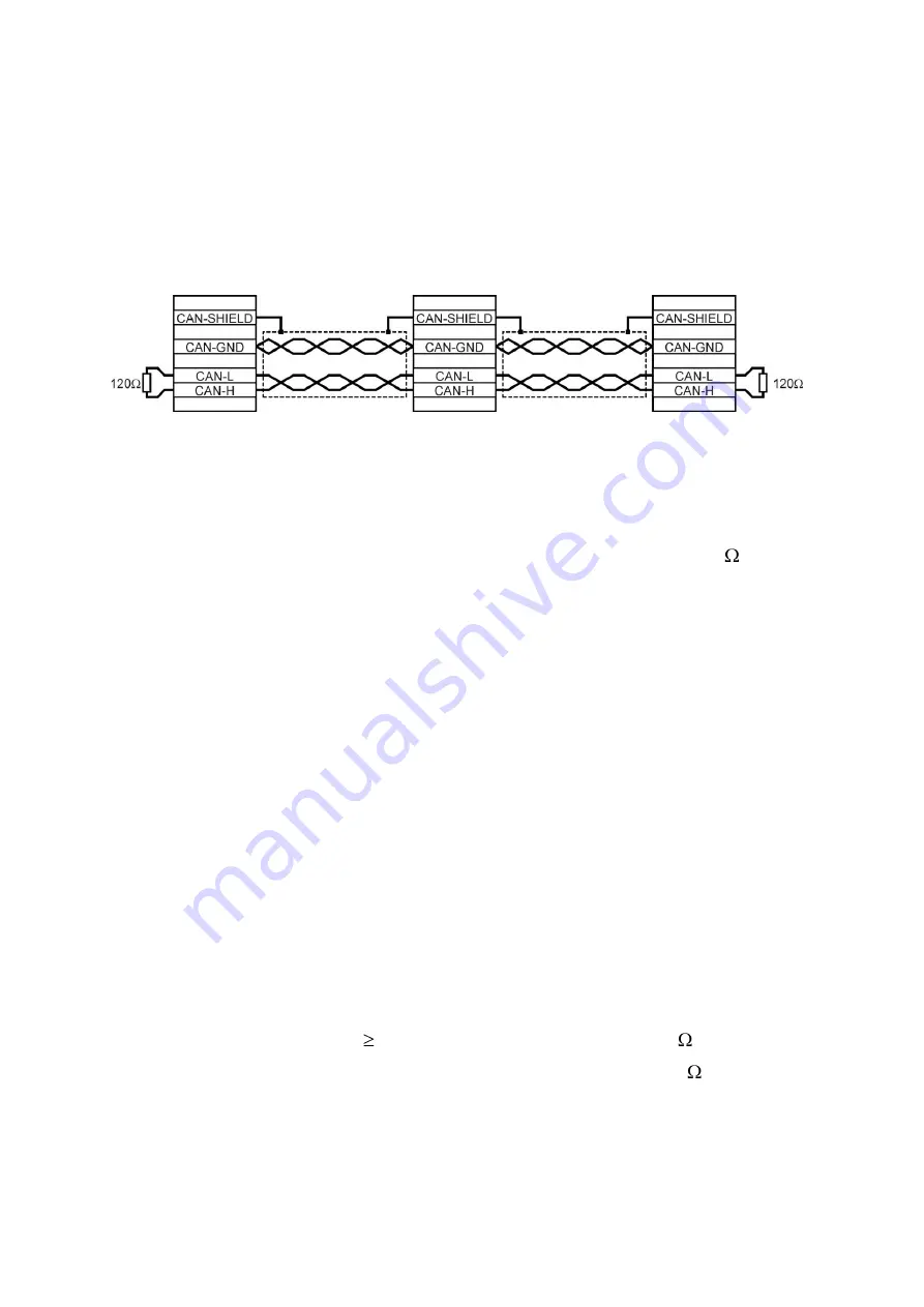
Fig. 3.2: Cabling example
-
The individual nodes of the network are connected point-to-point to each other, so the
CAN cable is looped from controller to controller (see Fig. 3.2).
-
At both ends of the CAN cable, there must be an end resistor of exactly 120 ±5 %.
Frequently, such an end resistor is already built into CAN cards or a PLC and must be
taken into account accordingly.
-
For cabling, a
shielded
cable with exactly two
twisted
lead pairs must be used.
A twisted lead pair is used to connect CAN-H and CAN-L.
The cores of the other pair are used
together
for CAN-GND.
The screen of the cable is guided onto the CAN Shield connections for all nodes.
A table with the technical data of usable cables is located at the end of this chapter.
-
Use of adapter plugs is not recommended for CAN bus cabling. But if this is still
necessary, make sure that metallic plug housings are used to connect the cable shield.
-
To keep disturbance as low as possible,
motor cable should not be laid parallel to signal lines,
motor cable designed in accordance with the specification,
motor cable properly shielded and earthed.
-
For additional information on the design of a disturbance-free CAN bus cabling,
we refer you to the
Controller Area Network protocol specification, version 2.0, from
Robert Bosch GmbH, 1991
.
-
Technical data, CAN bus cable:
2 pairs of 2 twisted leads, d 0.22 mm
2
Screened
Loop resistance < 0.2 /m
Impedance 100 … 120
Summary of Contents for CMMP Series
Page 2: ......


