


7. Device control
138
Festo P.BE-CMMP-CO-SW-EN 0708NH
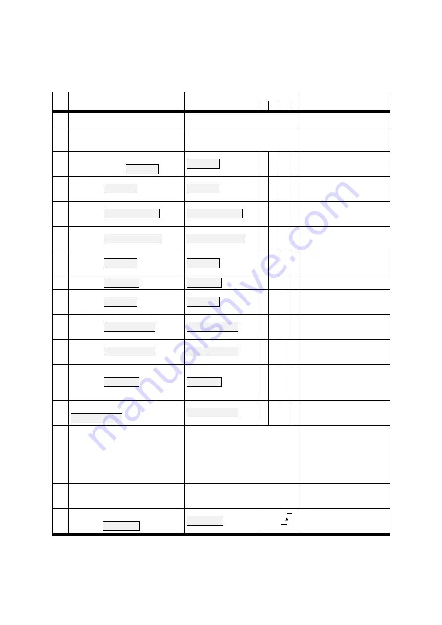
Condition diagram: Condition transitions
The following table lists all conditions and their meaning:
No. Is performed when
Bit combination (controlword)
Action
Bit
3 2 1 0
0
Switched on or reset occurs
Internal transition
Execute self-test
1
Self-test successful
Internal transition
Activation of CAN
communication
2
Final stage and regulator activated
prev. + command
Shutdown
Shutdown
=
x 1 1 0
-
3
Command
Switch On
Switch On
=
x 1 1 1
Switching on the final
stage
4
Command
Enable Operation
Enable Operation
=
1 1 1 1
Control in accordance with
set operating mode
5
Command
Disable Operation
Disable Operation
=
0 1 1 1
Final stage is blocked.
Motor rotates freely
6
Command
Shutdown
Shutdown
=
x 1 1 0
Final stage is blocked.
Motor rotates freely
7
Command
Quick Stop
Quick Stop
=
x 0 1 x
-
8
Command
Shutdown
Shutdown
=
x 1 1 0
Final stage is blocked.
Motor rotates freely
9
Command
Disable Voltage
Disable Voltage
=
x x 0 x
Final stage is blocked.
Motor rotates freely.
10 Command
Disable Voltage
Disable Voltage
=
x x 0 x
Final stage is blocked.
Motor rotates freely
11 Command
Quick Stop
Quick Stop
=
x 0 1 x
Braking is introduced in
accordance with
quick_stop_ option_code
.
12
Braking ended or command
Disable Voltage
Disable Voltage
=
x x 0 x
Final stage is blocked.
Motor rotates freely
13 Error occurred
Internal transition
In case of uncritical errors,
reaction according to
fault_
reaction_option_code
.
For critical errors,
transition 14 occurs
14 Error resolution is ended
Internal transition
Final stage is blocked.
Motor rotates freely
15
Error r
command
Fault Reset
Fault Reset
=
Bit 7 =
Acknowledge error
(with rising edge)
Summary of Contents for CMMP Series
Page 2: ......


