


17-17
Seiko Epson Corporation
S1C31D50 TECHNICAL MANUAL
(Rev. 1.00)
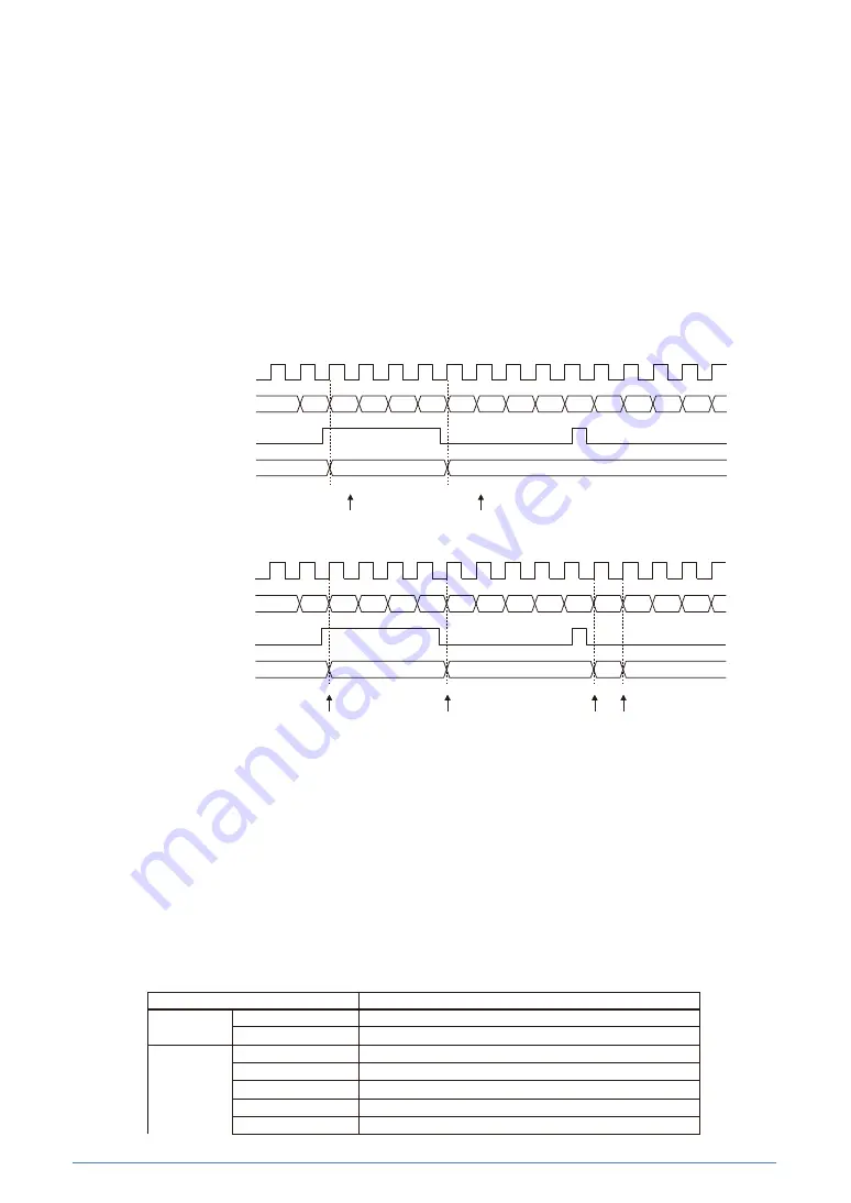
Synchronous capture mode/asynchronous capture mode
The capture circuit can operate in two operating modes: synchronous capture mode and
asynchronous capture mode.
Synchronous capture mode is provided to avoid the possibility of invalid data reading by capturing
counter data simultaneously with the counter being counted up/down. Set the T16B_
n
CCCTL
m
.SCS
bit to 1 to set the capture circuit to synchronous capture mode. This mode captures counter data
by synchronizing the capture signal with the counter clock.
On the other hand, asynchronous capture mode can capture counter data by detecting a trigger
pulse even if the pulse is shorter than the counter clock cycle that becomes invalid in synchronous
capture mode. Set the T16B_
n
CCCTL
m
.SCS bit to 0 to set the capture circuit to asynchronous capture
mode.
(1)
Synchronous capture mode
(2)
Asynchronous capture mode
Figure 17.4.3.4 Synchronous Capture Mode/Asynchronous Capture Mode
Capture data transfer using DMA
By setting the T16B_
n
CC
m
DMAEN.CC
m
DMAEN
x
bit to 1 (DMA transfer request enabled) in
capture mode, a DMA transfer request is sent to the DMA controller and the T16B_
n
CCR
m
register
value is transferred to the specified memory via DMA Ch.
x
when the T16B_
n
INTF.CMPCAP
m
IF bit is
set to 1 (when data has been captured).
This automates reading and saving of capture data.
The transfer source/destination and control data must be set for the DMA controller and the
relevant DMA channel must be enabled to start a DMA transfer in advance. For more information
on DMA, refer to
the “DMA Controller” chapte
r.
Table 17.4.3.2 DMA Data Structure Configuration Example (Capture Data Transfer)
Item
Setting example
End pointer
Transfer source
T16B_
n
CCR
m
register address
Transfer destination
Memory address to which the last capture data is stored
Control data
dst_inc
0x1 (+2)
dst_size
0x1 (haflword)
src_inc
0x3 (no increment)
src_size
0x1 (halfword)
R_power
0x0 (arbitrated for every transfer)
1
2
3
4
5
6
7
8
9
10
11
12
13
14
0
1
5
Count clock
T16B_
n
TC.TC[15:0]
Capture trigger signal
T16B_
n
CCR
m
.CC[15:0]
Capturing operation
(When T16B_
n
CCCTL
m
.CAPTRG[1:0] bits = 0x3)
1
2
3
4
5
6
7
8
9
10
11
12
13
14
0
1
5
10
11
Count clock
T16B_
n
TC.TC[15:0]
Capture trigger signal
T16B_
n
CCR
m
.CC[15:0]
Capturing operation
(When T16B_
n
CCCTL
m
.CAPTRG[1:0] bits = 0x3)
Summary of Contents for S1C31D50
Page 461: ...25 1 Seiko Epson Corporation S1C31D50 TECHNICAL MANUAL Rev 1 00 25 Package TQFP12 48PIN ...
Page 462: ...25 2 Seiko Epson Corporation S1C31D50 TECHNICAL MANUAL Rev 1 00 QFP13 64PIN ...
Page 463: ...25 3 Seiko Epson Corporation S1C31D50 TECHNICAL MANUAL Rev 1 00 TQFP14 80PIN ...
Page 464: ...25 4 Seiko Epson Corporation S1C31D50 TECHNICAL MANUAL Rev 1 00 QFP15 100PIN ...


