
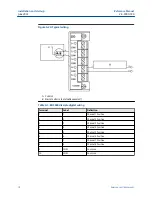


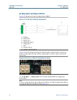


Analog inputs settings switches
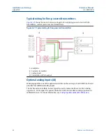
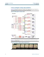
shows how to wire two analog inputs (
TB10
).
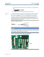
Figure 4-25: Customer wiring for analog inputs
A. Backplane
B. Analog inputs
C. Analog input 1
D. Analog input ground
E. Analog input 2
F. Cable
G. Customer devices
H. Customer 4-20 mA outputs
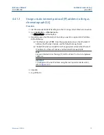
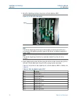
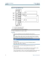
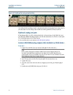
shows the factory settings for the analog input switches that are located on
the base input/output (I/O) board. These analog inputs are set to accept a current (4-20
mA) source.
Figure 4-26: Factory settings for analog input switches
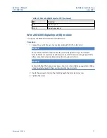
Use the
Hardware
→
Analog Inputs
menu in Rosemount MON2020 to configure the
analog inputs.
Note
To set an analog input to accept a voltage (0-10 VDC) source, flip the appropriate switch in
the opposite direction from that shown in
Installation and start-up
Reference Manual
June 2022
2-3-9000-744
84
Emerson.com/Rosemount
Summary of Contents for Rosemount 700XA
Page 1: ...Reference Manual 2 3 9000 744 Rev L June 2022 Rosemount 700XA Gas Chromatograph ...
Page 6: ...TxD TD or Sout Transmit data or signal out 6 ...
Page 30: ...Overview Reference Manual June 2022 2 3 9000 744 30 Emerson com Rosemount ...
Page 100: ...Installation and start up Reference Manual June 2022 2 3 9000 744 100 Emerson com Rosemount ...
Page 182: ...Operation and maintenance Reference Manual June 2022 2 3 9000 744 182 Emerson com Rosemount ...
Page 280: ......
Page 281: ......
Page 282: ......
Page 293: ......


