
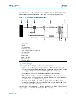
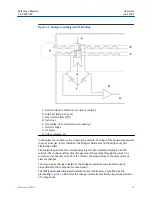


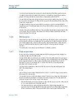

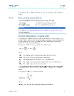


Figure 1-2: Analyzer assembly with TCD bridge
A. Detector block (in heated oven section of analyzer)
B. Reference flow (carrier gas)
C. Measurement flow ("MV")
D. Signal out
E. Preamplifier (in analyzer electronics housing)
F. Detector bridge
G. DC power
H. Valves, columns, etc.
In the quiescent condition, prior to injecting a sample, both legs of the bridge are exposed
to pure carrier gas. In this condition, the bridge is balanced, and the bridge output is
electrically nulled.
The analysis begins when the sample valve injects a fixed volume of sample into the
column. The continuous flow of carrier gas moves the sample through the column. As
successive components elute from the column, the temperature of the measurement
element changes.
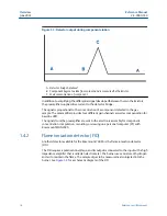
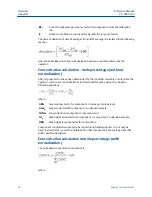
The temperature change unbalances the bridge and produces an electrical output
proportional to the component concentration.
The differential signal developed between the two thermistors is amplified by the
preamplifier.
illustrates the change in detector electrical output during elution
of a component.
Reference Manual
Overview
2-3-9000-744
June 2022
Rosemount 700XA
15
Summary of Contents for Rosemount 700XA
Page 1: ...Reference Manual 2 3 9000 744 Rev L June 2022 Rosemount 700XA Gas Chromatograph ...
Page 6: ...TxD TD or Sout Transmit data or signal out 6 ...
Page 30: ...Overview Reference Manual June 2022 2 3 9000 744 30 Emerson com Rosemount ...
Page 100: ...Installation and start up Reference Manual June 2022 2 3 9000 744 100 Emerson com Rosemount ...
Page 182: ...Operation and maintenance Reference Manual June 2022 2 3 9000 744 182 Emerson com Rosemount ...
Page 280: ......
Page 281: ......
Page 282: ......
Page 293: ......


