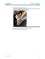
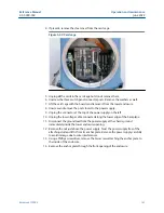

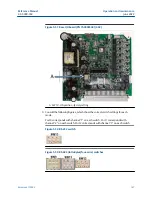


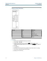


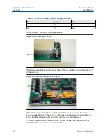


Figure 5-51: Base I/O board (PN 7A00403G01/G02)
A. SW10 - ON position - factory setting
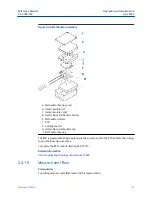
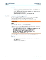
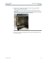
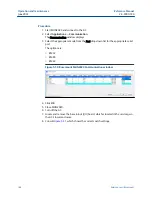
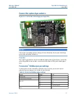
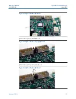
9. Consult the following figures, which show the correct switch settings for each
mode.
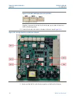
Port 0 corresponds with channel “1” on each switch; Port 1 corresponds with
channel “2” on each switch; Port 2 corresponds with channel “3” on each switch.
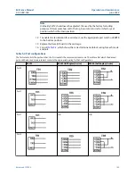
Figure 5-52: RS-232 switch
Figure 5-53: RS-422 (full duplex/four-wire) switches
Reference Manual
Operation and maintenance
2-3-9000-744
June 2022
Rosemount 700XA
167
Summary of Contents for Rosemount 700XA
Page 1: ...Reference Manual 2 3 9000 744 Rev L June 2022 Rosemount 700XA Gas Chromatograph ...
Page 6: ...TxD TD or Sout Transmit data or signal out 6 ...
Page 30: ...Overview Reference Manual June 2022 2 3 9000 744 30 Emerson com Rosemount ...
Page 100: ...Installation and start up Reference Manual June 2022 2 3 9000 744 100 Emerson com Rosemount ...
Page 182: ...Operation and maintenance Reference Manual June 2022 2 3 9000 744 182 Emerson com Rosemount ...
Page 280: ......
Page 281: ......
Page 282: ......
Page 293: ......


