1.
Follow the procedures in
Working on Your Computer
.
2.
Remove the computer cover (see
Removing the Computer Cover
).
3.
Unpack the new processor, being careful not to touch the underside of the processor.
4.
If the release lever on the socket is not fully extended, move it to that position.
5.
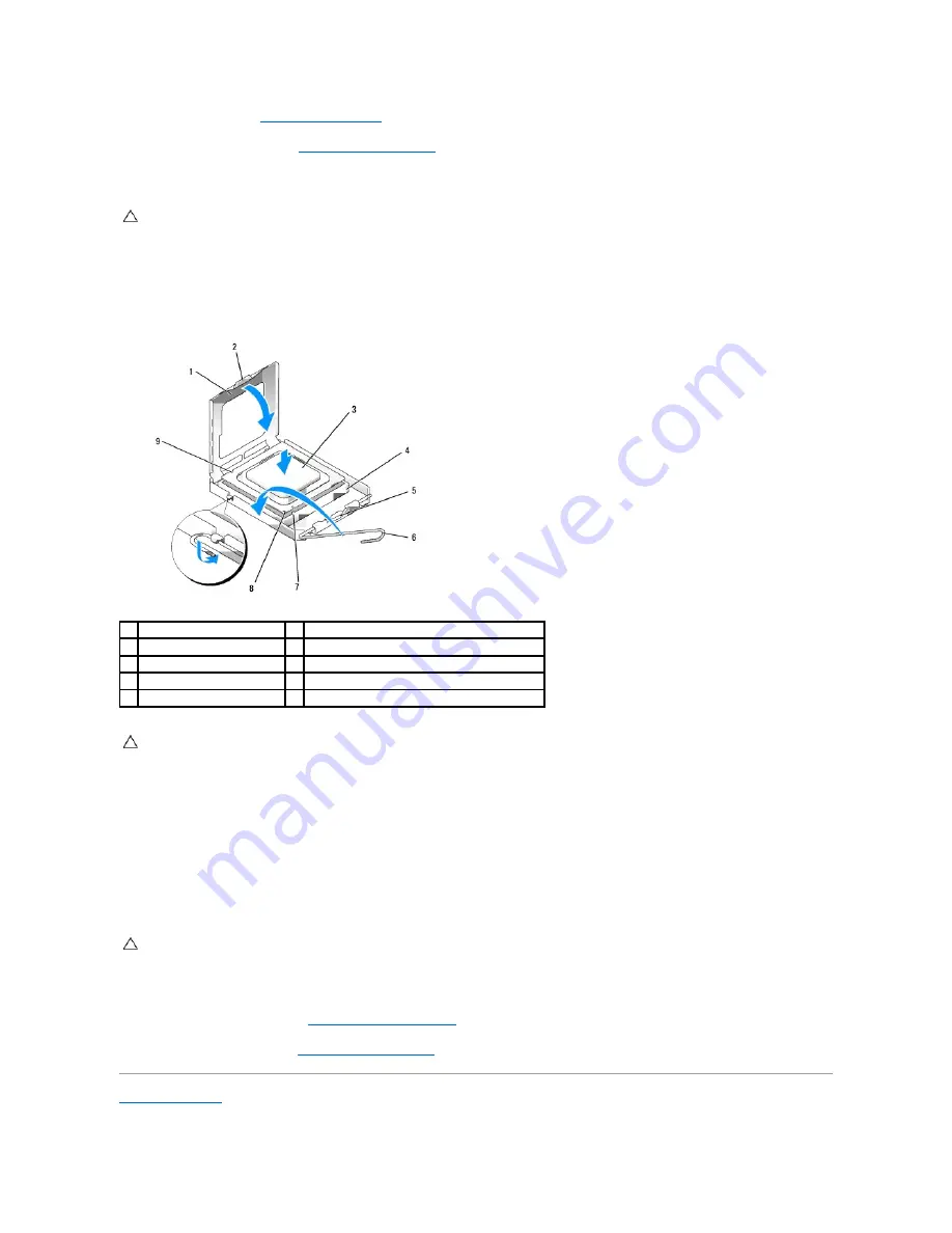
Orient the front and rear alignment-notches on the processor with the front and rear alignment-notches on the socket.
6.
Align the pin-1 corners of the processor and socket.
7.
Set the processor lightly in the socket and ensure that the processor is positioned correctly.
8.
When the processor is fully seated in the socket, close the processor cover.
Ensure that the tab on the processor cover is positioned underneath the center cover latch on the socket.
9.
Pivot the socket release lever back toward the socket, and snap it into place to secure the processor.
10.
Clean the thermal grease from the bottom of the heat sink.
11.
Apply the new thermal grease to the top of the processor.
12.
Install the heat sink assembly (see
Installing the Heat Sink Assembly
).
13.
Replace the computer cover (see
Replacing the Computer Cover
).
Back to Contents Page
CAUTION:
You must position the processor correctly in the socket to avoid permanent damage to the processor and the computer when you turn
on the computer.
1
processor cover
2
tab
3
processor
4
processor socket
5
center cover latch
6
release lever
7
front alignment-notch
8
socket and processor pin-1 indicator
9
rear alignment-notch
CAUTION:
To avoid damage, ensure that the processor aligns properly with the socket, and do not use excessive force when you install the
processor.
CAUTION:
Ensure that you apply new thermal grease. New thermal grease is critical for ensuring adequate thermal bonding, which is a
requirement for optimal processor operation.
Summary of Contents for OptiPlex 760
Page 29: ......
Page 48: ......
Page 101: ......
Page 106: ...Back to Contents Page 1 release knob ...
Page 140: ...5 Replace the computer cover 6 Turn on power to the computer Back to Contents Page ...
Page 143: ...Back to Contents Page 19 fan connector FAN_CPU ...
Page 146: ...Desktop System Board Screws Small Form Factor System Board Screws 1 screws 9 1 screws 9 ...
Page 148: ...Back to Contents Page ...
Page 157: ...Mini Tower Desktop Small Form Factor Ultra Small Form Factor ...
Page 194: ...7 Replace the cable cover if used Back to Contents Page ...
Page 196: ...Back to Contents Page ...
Page 199: ...5 Replace the computer cover 6 Turn on power to the computer Back to Contents Page ...


