The PWM output (0 to 100 %) is configured as a curve, in the same way as the other analogue outputs.
More information
See
Hardware characteristics and configuration
,
General characteristics
,
Analogue output characteristics and
configuration
.
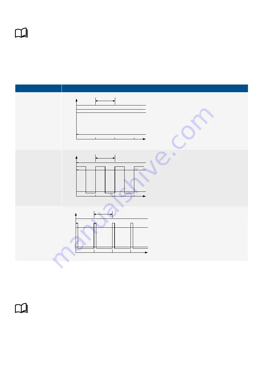
Duty cycles
The PWM uses duty cycles for its output. The PWM frequency determines the cycle length. One cycle is therefore 1/500 Hz = 0.002
seconds long, ±10 %. The following table illustrates the output for various duty cycles.
Table 13.38
Relationship between duty cycles and the PWM output
Duty cycle
Graph
100 %
Cycle
0
Voltage
[V]
time [s]
6.85
0.5
0.002
0.004
5.5
50 %
0
Voltage
[V]
time [s]
0.5
0.002
0.004
5.5
Cycle
6.85
12.5 %
0
5.5
Voltage
[V]
time [s]
0.5
0.002
0.004
0.006
Cycle
6.85
13.10.5 Analogue input (AI) characteristics
This analogue input can be configured as either current (0 to 24 mA) or voltage (-10 to 10 V). Using a configured or selected input
curve, the controller converts the input to a corresponding value. You can also configure the input to activate functions and/or
alarms.
More information
See
Hardware characteristics and configuration
,
General characteristics
,
Analogue input characteristics and
configuration
.
Galvanic connection
The two analogue inputs on GAM3.1 are galvanically connected. You therefore cannot use the analogue inputs on GAM3.1 in series
with each other (for example, for a back-up measurement).
DESIGNER'S HANDBOOK 4189340911K UK
Page 455 of 521


