Parameters
Configure the parameters under
Configure > Parameters > Local > 4th current input > Neutral inverse time over-current
.
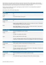
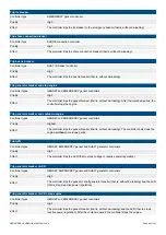
Table 3.65
Default parameters
Parameter
Range
Neutral inverse time
over-current
Curve
See the reference
IEC Inverse
Limit (the set point, also known as LIM)
2 to 200 % of nominal current (4th current input)
30 %
Time multiplier setting (TMS)
0.01 to 100.0
1.0
Threshold
1.0 to 1.3
1.1
k (only used if custom curve is selected)
0.001 s to 2 min
0.14 s
c (only used if custom curve is selected)
0 s to 1 min
0 s
alpha (α, or a) (only used if custom curve is
selected)
0.001 to 1
0.02
Enable
Not enabled, Enabled
Enabled
Latch
Not enabled, Enabled
Enabled
Alarm action
Trip [Breaker]
More information
See
Source AC protections
,
Inverse time over-current (ANSI 51)
in this chapter for the calculation method, the
standard curves, and information about the definite time characteristic.
3.7 ACM voltage measurement errors
3.7.1 [Source]/[Busbar] L1-L2-L3 wire break
Controller types: GENSET, SHAFT generator, SHORE connection and BUS TIE breaker controllers
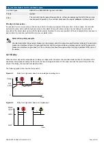
These alarms alert the operator to a voltage measurement failure:
•
[Source] L1-L2-L3 wire break
•
[Busbar] L1-L2-L3 wire break
The controller only activates the alarm when all of these conditions are met:
•
The generator breaker is closed
•
Voltage is detected by one set of ACM voltage measurements
•
No voltage is detected on all three phases for the other set of ACM voltage
measurements
0
1
Time
Busbar
L1-L2-L3
Wire break
L1
L2
L3
Generator
voltage
L1
L2
L3
Busbar
voltage
Parameters
Configure > Parameters > [Source] > AC setup > Multiple phase wire break
DESIGNER'S HANDBOOK 4189340911K UK
Page 87 of 521


