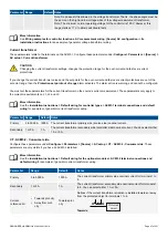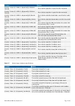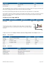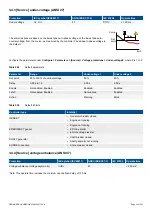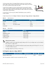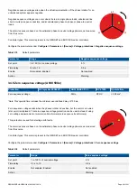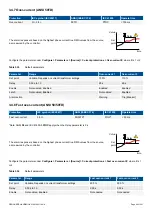
Table 3.21
4th current input frequency analogue output function
Function
Details
Local > 4th current input > Frequency (f) > L4 [Hz]
The controller outputs the 4th frequency (based on the 4th current
measurement).
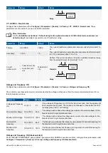
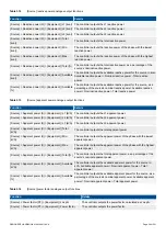
Table 3.22
4th current input power analogue output function
Function
Details
Local > 4th current input > Power (P) > L4 [kW]
The controller outputs the 4th power (based on the 4th current measurement and
the [Busbar] L1 voltage).
Table 3.23
4th current input reactive power analogue output function
Function
Details
Local > 4th current input > Reactive power (Q) > L4
[kvar]
The controller outputs the 4th reactive power (based on the 4th current
measurement and the [Busbar] voltage).
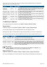
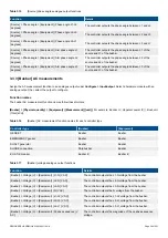
Table 3.24
4th current input apparent power analogue output function
Function
Details
Local > 4th current input > Apparent power (S) > L4 [kVA]
The controller outputs the 4th apparent power (based on the 4th
current measurement and the [Busbar] voltage).
Table 3.25
4th current input power factor analogue output functions
Function
Details
Local >4th current input > Power factor (PF) > L4 | cos
phi
The controller outputs the power factor, calculated as cos phi (based on
the 4th current measurement and the [Busbar] voltage).
Local > 4th current input > Power factor (PF) > L4 |
Power factor
The controller outputs the power factor (based on the 4th current
measurement and the [Busbar] voltage).
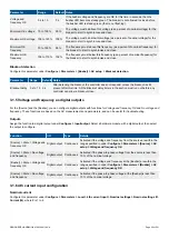
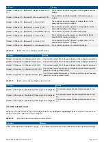
Table 3.26
4th current input phase angle analogue output function
Function
Details
Local > 4th current input > Phase angle > L4
[degrees]
The controller outputs the phase angle between the 4th current
measurement and the [Busbar] L1 voltage measurement.
3.4 Source AC protections
3.4.1 Information about protections
This section describes the AC protections based on the controller's measurements on the [Source] side of the breaker.
Controller type
Source
Breaker
GENSET
Diesel genset
GB
EMERGENCY genset*
Emergency diesel genset
EGB and TB*
SHAFT generator
Shaft generator
SGB
DESIGNER'S HANDBOOK 4189340911K UK
Page 61 of 521

