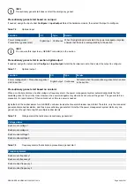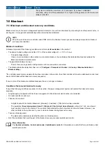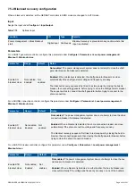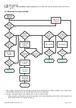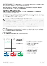
The following graph of PMS available power shows an example of the hysteresis between the stop and start for the power method.
The section consists of two equally sized gensets. The start and stop delays are 0 seconds. At the beginning of the period shown on
the graph, the section is unpowered.
G
e
n
se
t 1
s
ta
rts
G
e
n
se
t 2
s
to
p
s
G
e
n
se
t 2
s
ta
rts
Hysteresis
Stop
limit
Start
limit
Nominal power
Available power
Consumed power
1
2
3
4
5
6
7
Power
[kW]
time
0
1. The PMS available power jumps up when genset 1 starts and connects to the busbar.
2. As time passes, the section load increases, which makes the PMS available power fall.
3. The PMS available power falls until it reaches the load-dependent start limit. Genset 2 is started.
4. The PMS available power jumps up when genset 2 starts, then drops as the section load continues to increase.
5. The section load decreases, and the available power increases, until PMS available power = genset 2 nominal power + load-
dependent stop limit.
6. Genset 2 stops. The PMS available power drops to the load-dependent stop limit.
7. The section load continues to decrease, and the PMS available power continues to increase.
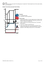
INFO
The hysteresis for the percent method works differently. See
Percent method and hysteresis
.
7.4.8 Percent method for load-dependent start and stop
For the
Percent
method, the power management system (PMS) starts/stops gensets with GENSET controllers in AUTO mode based
on the load measured at each genset.
The controller calculates the genset load percentage:
Genset load percentage = Measured genset load / Nominal genset power
The
Percent
method is a simple, robust method. However, the available power is proportional to the section load. The available
power may therefore be too low at low loads, and/or too high at high loads. If this is a problem, use the
Power
method.
Load-dependent start
If the genset load percentage is higher than the
Load-dependent start
limit, then the first genset that is ready to start (in the priority
order) is started and connected.
DESIGNER'S HANDBOOK 4189340911K UK
Page 236 of 521


