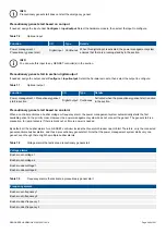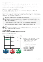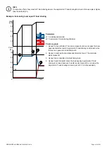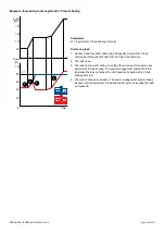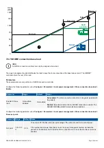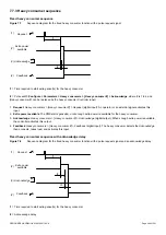
Example: Decreasing load
A
G
B
G
C
G
1
100
20
60
0
40
80
130
170
150
190
Power
[%]
Load
[kW]
Time
s3
s2
s1
2
3
4
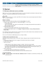
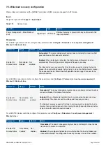
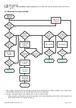
Parameters
s1 = Asymmetric P load sharing
Set point
s2 = Load-dependent stop
s3 = Asymmetric P load sharing
Minimum
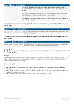
Points on graph
1. The load decreases.
2. Genset C reaches the asymmetric P load sharing minimum.
3. The power management system shares the load equally between
Genset A, Genset B and Genset C.
4. The load decreases, and so the power management system stops
Genset C. Genset A runs at its asymmetric P load sharing set point and
the load on Genset B varies.
7.6.5 Asymmetric Q load sharing
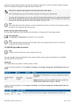
Asymmetric reactive power (Q) load sharing allows you to select certain gensets to run at their optimum reactive power load
efficiency. The reactive power load on the other gensets then fluctuates to absorb variations.
Asymmetric Q load sharing can also be configured so that, as far as possible, a particular genset supplies a base reactive power
load.
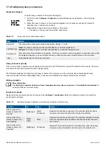
Asymmetric Q load sharing is done by the power management system over the DEIF network.
Hardware
The following hardware is required for asymmetric Q load sharing.
Name
Details
DEIF network
The DEIF network is used for asymmetric Q load sharing.
AVR control
The controller must control the genset AVR for reactive power load sharing.
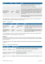
Control types
For controllers under power management system control (that is, in AUTO or SEMI mode), if enabled, the power management
system uses asymmetric Q load sharing to share the load between the connected equipment. The shared reactive load may be the
total system reactive power load. However, if a connected controller is under switchboard control, then the shared reactive power
load is the remaining reactive power load.
If a controller is under switchboard control, then that controller does not control its reactive load, and therefore it cannot participate in
reactive power load sharing.
DESIGNER'S HANDBOOK 4189340911K UK
Page 254 of 521

