Analogue PID controller
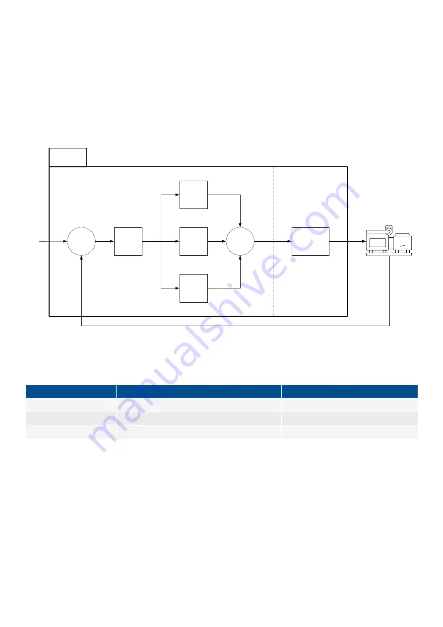
A schematic of the analogue PID controller is given below. Analogue control is continuous, and consists of these steps:
1. The controller measures the operating value(s).
2. The controller deducts the measured value from the reference value (that is, the set point) to determine the error (also known as
the deviation).
3. The controller modifies the error using a PID controller, and sends the result to the output modifier.
4. The output modifier converts the modified error to a suitable signal for the governor or AVR.
5. The governor or AVR then adjusts the genset.
Figure 6.1
Simplified overview of the analogue PID controller
∑
Gain
(Kp)
I-part
(Ti)
P-part
(1)
D-part
(Td)
∑
Output
modifier
-
R
e
fe
re
n
ce
v
a
lu
e
Measured value
Controller
G
PID control
The PID controller consists of three parts.
Part
Contribution (Laplace domain)
Configurable parameters
Proportional part
1
Kp
Integral part
1 / ( Ti x s )
Kp, Ti
Derivative part
Td x s
Kp, Td
Gain
The gain (
Kp
) determines the amplitude of a signal. The amplitude increases for a gain higher than 1, and decreases for a gain
between 0 and 1.
The same gain (
Kp
) is applied to
each part
of the analogue controller. That is, increasing the gain not only increases the
proportional part, but also increases the integral part and the derivative part.
Proportional part
The proportional part contributes the amplified error to the PID output.
Gain (
Kp
) is the only term in the proportional part of the controller. That is, the contribution of the proportional part of the controller is
directly proportional to the calculated error. For example, if
Kp
is 15 and the calculated error is +0.02, the proportional contribution is
+0.30.
DESIGNER'S HANDBOOK 4189340911K UK
Page 169 of 521


