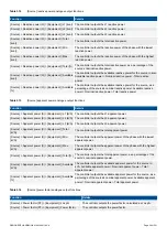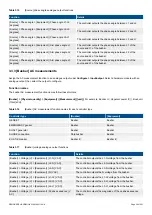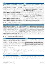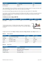
Figure 3.2
Inverse time over-current time characteristic graph
t(G)
[s]
G
G
D
G
S
2 G
S
G
T
(1.1 G
S
)
In this controller, if the rated secondary current of the current measurement transformer is
1 A
(that is, the current transformer rating
is -/1 A), then
G
D
= 17.5 × I
CT primary
for this protection. However, if the rated secondary current of the current transformer is
5 A
(that is, -/5 A), then
G
D
= 3.5 × I
CT primary
.
Influence of the CT primary current rating on G
D
example
A current transformer has a primary rating of 500 A and a secondary rating of 5 A. The nominal current of the system is
350 A, and the three-phase inverse time over-current alarm
Limit
is 100 %.
G
D
of the inverse time over-current characteristic graph according to IEC60255 is 7000 A.
•
G
D
= 20 × G
S
= 20 × (I
nom
× (Limit / 100)) = 20 × (350 × (1 / 1)) = 7000 A
However, the highest G
D
value where measurements can be made is 1750 A.
•
Because the secondary current rating is 5 A, the formula to calculate the measurable G
D
is G
D
= 3.5 × I
CT primary
.
•
G
D
= 3.5 × I
CT primary
= 3.5 × 500 = 1750 A
INFO
If the performance of the inverse time over-current protection is important, DEIF recommends using a current transformer
that is rated for a 1 A secondary current (that is, -/1 A).
3.4.12 Negative sequence current (ANSI 46)
Protection
IEC symbol (IEC60617)
ANSI (IEEE C37.2)
IEC 61850
Operate time
Negative sequence current
46
PUBC
< 200 ms*
*Note: This operate time includes the minimum user-defined delay of 100 ms.
DESIGNER'S HANDBOOK 4189340911K UK
Page 72 of 521

