More information
See
Alarms > Tasks > Perform an alarm test
in the
PICUS manual
for more information about the alarm test buttons
available on the
Alarms
page in PICUS.
4.2.13 Additional alarm information
The additional alarm information provides information about the state of the alarm. This information can be useful during
commissioning and trouble shooting.
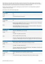
Table 4.2
Additional alarm information
Information
Notes
Actual value
Shows the operating value of the alarm.
Timer remaining
Shows the remaining delay time before the alarm activates.
Counter
Counts how many times the alarm was activated. The amount shown also includes activation during an
alarm test.
State
Shows the state of the alarm.
More information
See
Alarms > Alarm handling
for a detailed description of each alarm state.
Test state
Shows if an alarm test is in progress (
Active
) or not in progress (
Inactive
) for the alarm.
Reset counter value Changes the
Counter
parameter value to the selected value.
4.3 Customised inhibits
4.3.1 Configuring customised inhibits
In addition to the default inhibits, you can also use three custom inhibit functions (
Inhibit 1
,
Inhibit 2
and
Inhibit 3
). You can activate a
custom inhibit using a digital input, PICUS, Modbus, and/or CustomLogic.
INFO
Each controller can have a maximum of three customised inhibits configured.
Inputs
Assign the inhibit function under
Configure > Input/output
. Select the hardware module, then select the input to configure.
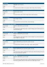
Table 4.3
Hardware required in addition to the minimum standard controller wiring
Function
I/O
Type
Details
Alarm system > Inhibits > Activate inhibit #,
where # is 1 to 3
Digital input Continuous
When the digital input is activated, then the controller
applies
Inhibit #
, where # is 1 to 3.
INFO
If you use CustomLogic, you do not have to wire up a digital input, and assign the
Activate inhibit #
function to the input.
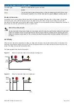
Parameters
Select the customised inhibit under
Configure > Parameters > [Alarm] > Inhibit > #[number]
, where [Alarm] represents any alarm,
and [number] represents the number of the inhibit field.
DESIGNER'S HANDBOOK 4189340911K UK
Page 102 of 521


