More information
See
AC configuration and nominal settings
,
Nominal settings
,
Nominal power calculations
for more information.
Ship busbar nominal settings
These settings are under
Configure > Parameters > Busbar > Nominal settings > Nominal settings #
, where # is 1 to 4.
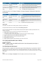
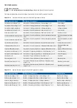
Table 11.2
Controller nominal settings
Nominal setting Range
Default Notes
Voltage (V)
10 V to 160 kV 400V
The phase-to-phase nominal voltage for the busbar. If there is no transformer
between the shore connection and the ship busbar, the nominal voltage for the busbar
will be the same as the nominal voltage for the shore connection.
Frequency (f)
48 to 62 Hz
50 Hz
The system nominal frequency. All the controllers in the system should have the same
nominal frequency.
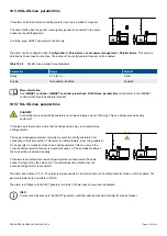
11.2.3 Power management
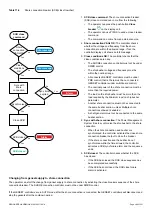
The SHORE connection controller works together with the other controllers in the system to provide efficient power management.
More information
See
Power management
for more information.
11.2.4 AC configuration
More information
The
AC configuration and nominal settings
chapter describes the AC configuration in general.
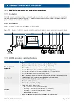
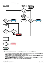
The following table shows how the general AC configuration description applies to the SHORE connection controller.
Table 11.3
AC configuration for the SHORE connection controller
SHORE connection
General name
Shore busbar
[Source]
Ship busbar
[Busbar]
11.2.5 Breaker configuration
More information
See
Breakers, synchronisation and de-loading
for more information about breaker configuration in general. For the
SHORE connection controller, replace "[Breaker]" with "Shore connection breaker" in these descriptions.
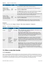
The following inputs and parameters are in addition to the general breaker configuration.
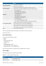
Inputs
The following inputs are not part of the breaker configuration and are optional. They can be used for commands to the controller.
Assign the inputs under
Configure > Input/output
. Select the hardware module, then select the input to configure.
DESIGNER'S HANDBOOK 4189340911K UK
Page 379 of 521


