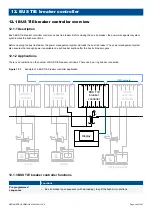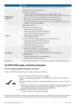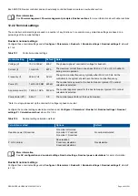
Figure 13.1
Example of a voltage decrease over a diode
0 V
24 V DC
0 V DC
F1
24 V DC
0 V DC
F2
Supply 1
Supply 2
+
-
23.3 V
∆V = 0.7 V
Heat emission
For the heat emission from the equipment, use the maximum power consumption for the power supply (or power supplies).
13.2.3 Relay output characteristics and configuration
Symbol
Hardware modules
PSM3.1
EIM3.1
GAM3.1
GAM3.2
DU 300 (terminals 6,7)
IOM3.1
DU 300 (terminals 3,4,5)
The controller can use relay outputs for many purposes. Examples: Activate alarm devices, open and close breakers, and genset
speed and voltage regulation.
Configuration
All relay outputs are configurable, except for PSM3.1 terminals 3,4 (
Status OK
), GAM3.2 terminals 14,15 (
GAM3.2 1 Status OK
),
and the DU 300 relays. A controller can have a number of relay outputs.
You can assign a digital output function or an alarm for a relay output.
You can also create customised digital output functions using CustomLogic, and assign a relay output.
Controller types and single-line diagram
The controller type determines which digital output functions are available.
DESIGNER'S HANDBOOK 4189340911K UK
Page 414 of 521


