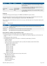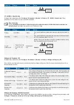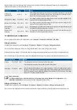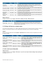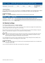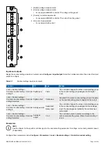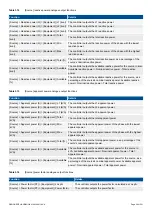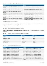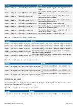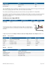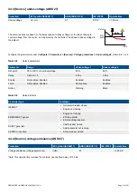
During a blackout, the controller uses these parameters to calculate whether the voltage and frequency from the generator
measurements are OK, so that the breaker can close.
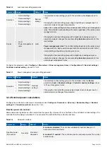
Parameter
Range
Default Notes
Voltage and
frequency OK
0 s to 1 h
2 s
If the voltage and frequency from the source are OK for this time in seconds, then
the equipment LED becomes steady green. The breaker is not allowed to close
before the LED is steady green (that is, not flashing).
Minimum OK voltage 70 to 100 %
95 %
The voltage must be above this voltage (as a percent of nominal voltage) for the
breaker to start to synchronise and close.
Maximum OK voltage 100 to 120 % 105 %
The voltage must be below this voltage (as a percent of nominal voltage) for the
breaker to start to synchronise and close.
Minimum OK
frequency
70 to 100 %
94 %
The frequency must above this frequency (as a percent of nominal frequency) for
the breaker to start to synchronise and close.
Maximum OK
frequency
100 to 110 % 106 %
The frequency must below this frequency (as a percent of nominal frequency) for
the breaker to start to synchronise and close.
3.1.4 [Busbar] AC configuration
You can configure the busbar's AC configuration under
Configure > Parameters > [Busbar] > AC setup
.
Voltage transformer
Configure these parameters under
Configure > Parameters > [Busbar] > AC setup > Voltage transformer
.
You must set these parameters if there are voltage transformers on the busbar voltage measurement.
If
Primary
:
Secondary
ratio is 1, the controller uses the voltage measurement without any correction for a voltage transformer.
The controller does not need information about the voltage transformer type (for example, open delta, star-delta, and so on).
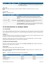
Parameter Range
Default Notes
Primary
10 to 160 kV 400 V
The voltage transformer primary side (busbar side) value.
Secondary 17 to 690 V
400 V
The voltage transformer secondary side (controller side) value.
Note: No phase shift is allowed in the voltage transformer. That is, the phase angle must be
the same on the high and low voltage sides of the busbar voltage measurement transformer.
Note: The minimum normal operating voltage for the controller is 100 V. However, this range
starts at 17 V to allow switchboard tests.
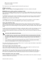
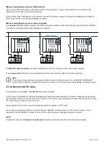
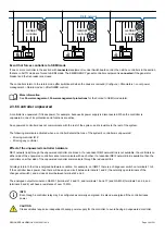
More information
See
Wiring examples for controller functions
,
AC measurement wiring
,
[Busbar] AC configuration
in the
Installation instructions
for an example of busbar voltage transformer wiring.
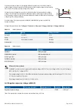
Voltage and frequency OK
Configure these parameters under
Configure > Parameters > [Busbar] > AC setup > Voltage and frequency OK
.
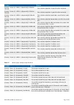
The controller uses these parameters to calculate whether the voltage and frequency from the busbar measurements are OK.
DESIGNER'S HANDBOOK 4189340911K UK
Page 49 of 521

