Parameter Range
Default Notes
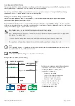
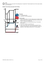
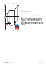
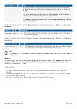
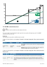
If the system load is higher than this set point, the power management system transfers the
load to the gensets so that the shore connection runs at the
Set point
.
If the gensets are running at the
Maximum limit
, the power management system increases the
load on the shore connection.
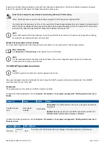
Configure the following parameter under
Configure > Parameters > Local power management > Shore connection base load >
Min. set point
.
Parameter
Range
Default Notes
Minimum limit 1 to 100 % 5 %
The minimum limit for the load on each genset (while using base load), as a percentage of
the genset nominal power.
Configure the following parameter under
Configure > Parameters > Local power management > Shore connection base load >
Max. set point
.
Parameter
Range
Default Notes
Maximum limit 1 to 120 % 95 %
The maximum limit for the load on each genset (while using base load), as a percentage of
genset nominal power. This maximum limit prevents genset overload.
INFO
The only way to run the shore connection in long-term parallel with gensets is by enabling and configuring a base load for
the shore connection.
7.6.8 DEIF network load sharing failure
The
P load sharing failure
and
Q load sharing failure
alarms alert the operator to the failure of the DEIF network load sharing. Other
alarms are also activated if communication is lost in the DEIF network.
More information
See
Regulation
,
Regulation alarms
for more information about load sharing failure alarms.
7.7 Heavy consumer management
7.7.1 Introduction
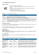
The heavy consumer function ensures that enough power is available when the heavy consumers need it. In addition, heavy
consumer management minimises the disruption to the rest of the system when the heavy consumers connect. Each controller can
manage up to four heavy consumers. The controller manages the heavy consumer function across the DEIF network.
A heavy consumer can be assigned to any controller.
For the heavy consumer function, the power from connected gensets in SEMI mode is included in the available power. However, for
load-dependent start, this power is not included in the PMS available power. The power management system may therefore start
additional gensets after the heavy consumer connects.
INFO
The heavy consumers must be assigned to the controller on the single-line diagram in order for the heavy consumer
functions to be visible under the controller inputs and outputs.
INFO
The heavy consumer functions may be assigned to any inputs and outputs on the controller. The inputs and outputs do not
have to be on the same hardware module.
DESIGNER'S HANDBOOK 4189340911K UK
Page 260 of 521


