Chapter 6 - Parameter Description [I/O]
6-40
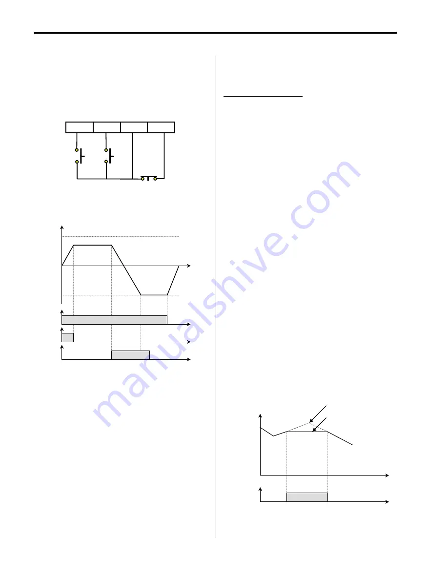
[3-Wire]
This function is for 3-wire start/stop control.
This function is mainly used with a momentary push button
to hold the current frequency output during acceleration or
deceleration.
[Wiring for 3-Wire Operation, P2 set to ‘3-Wire’]
[3-Wire Operation]
[Ext Trip-A]
This is a normally open contact input. When a terminal set
to ‘Ext Trip-A’ is ON, inverter displays the fault and cuts off
its output. This can be used as an external latch trip.
[Ext Trip-B]
This is a normally closed contact input. When a terminal
set to ‘Ext Trip-B’ is OFF, inverter displays the fault and
cuts off its output. This can be used as an external latch
trip.
[iTerm Clear]
This function is used for PID control. When this terminal is
ON, the accumulated value by I-Gain is set to ‘0’. Refer to
PID Control Block Diagram.
[Open-loop]
This is used to exchange the control mode of inverter from
PID mode (Close Loop) to V/F mode (Open Loop).
DRV-03 [Drive Mode] and DRV-04 [Frequency Mode] are
applied when the mode has been changed.
☞
Note:
This function can be used only when the inverter is
stopped.
[Main-drive]
When an option board (like RS485, DeviceNet, F-Net) is
installed and used for the frequency setting and the
run/stop command, the inverter operation can be changed
to manual operation using this function without changing
parameters.
FU1-02 [Frequency Mode] and FU1-01 [Drive Mode] are
applied when the mode has been changed.
☞
Note:
this function can be used only when the inverter is
stopped.
[Analog hold]
When there is an analog input signal for frequency
reference and ‘Analog hold’ terminal is ON, inverter fixes
its output frequency regardless of the frequency reference
change. The changed frequency reference is applied when
the terminal is OFF.
This function is useful when a system requires constant
speed after acceleration.
[Analog hold Operation]
FX
RX
P2
CM
P2-CM
ON
Output Frequency
Time
Time
FX-CM ON
Time
RX-CM
ON
Time
Freq.
Max.
Freq.
max.
P1-CM
‘Analog hold’
Reference Frequency,
Output frequency
Time
ON
Time
Reference Frequency
Output Frequency
Summary of Contents for 30 HP30
Page 6: ......
Page 12: ......
Page 16: ...Chapter 1 Installation 1 4 BLANK ...
Page 18: ...Chapter 1 Installation 1 6 BLANK ...
Page 28: ...Chapter 1 Installation 1 16 Notes ...
Page 39: ...Chapter 2 Operation 2 11 Notes ...
Page 40: ......
Page 46: ......
Page 60: ...Chapter 4 Operation Examples 4 14 Notes ...
Page 83: ...Chapter 5 Parameter List 5 23 Notes ...
Page 84: ......
Page 92: ...Chapter 6 Parameter Description DRV 6 8 Notes ...
Page 105: ......
Page 106: ...Chapter 6 Parameter description FU1 6 14 Notes ...
Page 126: ...Chapter 6 Parameter Description FU2 6 34 Notes ...
Page 144: ...Chapter 6 Parameter Description I O 6 52 Notes ...
Page 162: ......
Page 188: ...Chapter 7 Options 7 26 Type 1 Max 400 Watt Type 2 Max 600 Watt A ...
Page 189: ...Chapter 7 Options 7 27 Type 3 ...
Page 194: ......
Page 204: ......
Page 210: ......


