


Chapter 7 - Options
7-5
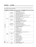
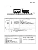
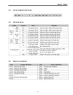
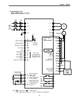
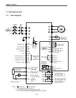
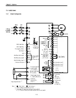
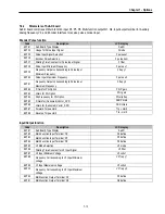
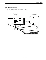
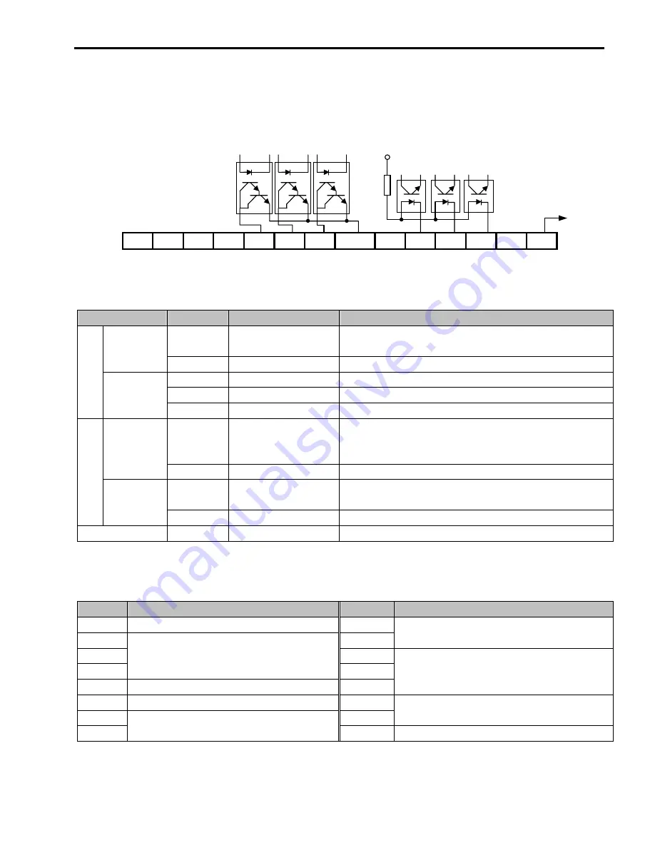
7.1.2 Terminal
Configuration
VR
V2
5G
NC
Q1
Q2
Q3 EXTG NC
P4
P5
P6
LM CM
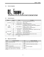
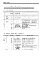
7.1.3 Terminal
Description
Section
Terminal
Name
Description
P4, P5, P6
Multi-Function Input
Used as the extended function of P1, P2, P3
(I/O-12 ~ I/O-14)
Contact Input
CM
Common Terminal
Common terminal for P4, P5, P6
VR
Power Supply for V2
DC voltage output terminal for V2 (+12V, 10mA)
V2
Analog Voltage Input
Analog voltage input terminal for frequency reference or override.
Input
Analog
Frequency
Reference
5G
Common Terminal
Common terminal for VR and V2
LM Load
Meter
Used to monitor one of Output Frequency, Output Current, Output
Voltage, DC link Voltage.
(+15V Pulse output, Average voltage: 0 ~ 10V DC)
+15V Pulse
Output
CM
Common Terminal
Common terminal for LM
Q1, Q2, Q3
Multi-Function Output
(Open-Collector Output)
Used as the extended function of AXA, AXC (I/O-44)
Output
Open Collector
Output
EXTG
External Common Terminal Common terminal for Q1, Q2, Q3
NC
Not
Used
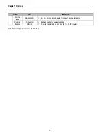
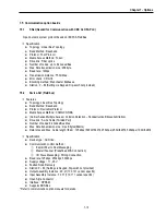
7.1.4
Parameters of Sub-A Board
Code
Parameter Description
Code
Parameter Description
EXT-01 Sub Board Type Display
EXT-09
EXT-02 EXT-10
Analog Voltage Input Signal (V2) Adjustment
EXT-03 EXT-30
EXT-04
Multi-Function Input Terminal (P4, P4, P6) Define
EXT-31
EXT-05 V2 Mode Selection
EXT-32
Multi-Function Output Terminal (Q1, Q2, Q3) Define
EXT-06 Filtering Time Constant for V2 Input Signal
EXT-34
EXT-07 EXT-35
LM Output Adjustment
EXT-08
Analog Voltage Input Signal (V2) Adjustment
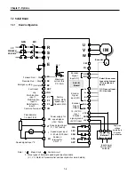
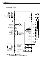
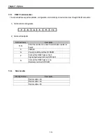
+24V DC
24V
Ground
Summary of Contents for 30 HP30
Page 6: ......
Page 12: ......
Page 16: ...Chapter 1 Installation 1 4 BLANK ...
Page 18: ...Chapter 1 Installation 1 6 BLANK ...
Page 28: ...Chapter 1 Installation 1 16 Notes ...
Page 39: ...Chapter 2 Operation 2 11 Notes ...
Page 40: ......
Page 46: ......
Page 60: ...Chapter 4 Operation Examples 4 14 Notes ...
Page 83: ...Chapter 5 Parameter List 5 23 Notes ...
Page 84: ......
Page 92: ...Chapter 6 Parameter Description DRV 6 8 Notes ...
Page 105: ......
Page 106: ...Chapter 6 Parameter description FU1 6 14 Notes ...
Page 126: ...Chapter 6 Parameter Description FU2 6 34 Notes ...
Page 144: ...Chapter 6 Parameter Description I O 6 52 Notes ...
Page 162: ......
Page 188: ...Chapter 7 Options 7 26 Type 1 Max 400 Watt Type 2 Max 600 Watt A ...
Page 189: ...Chapter 7 Options 7 27 Type 3 ...
Page 194: ......
Page 204: ......
Page 210: ......


