Chapter 1 - Installation
1-13
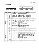
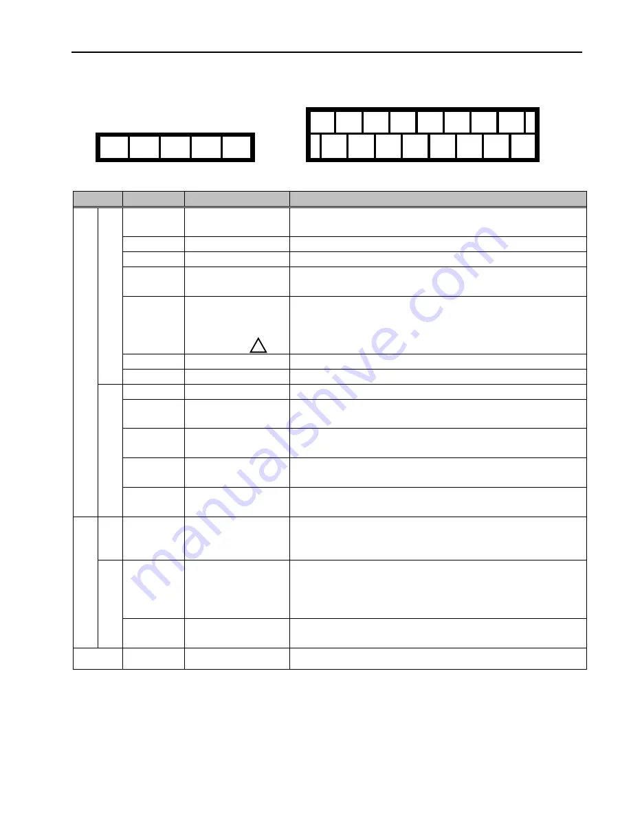
1.8 Control Terminals
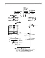
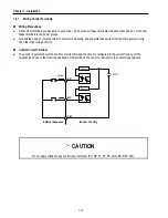
P1 P2 P3 FX RX NC VR V1
30A 30C 30B AXA AXC
JOG CM CM BX RST I FM 5G
Type
Symbol
Name
Description
P1, P2, P3
Multi-Function Input
1, 2, 3
Used for Multi-Function Input Terminal.
(Factory default is set to “Step Frequency 1, 2, 3”.)
FX
Forward Run Command
Forward Run When Closed and Stopped When Open.
RX
Reverse Run Command
Reverse Run When Closed and Stopped When Open.
JOG
Jog Frequency
Reference
Runs at Jog Frequency when the Jog Signal is ON. The Direction is set by
the FX (or RX) Signal.
BX Emergency
Stop
When the BX Signal is ON the Output of the Inverter is Turned Off. When
Motor uses an Electrical Brake to Stop, BX is used to Turn Off the Output
Signal. When BX Signal is OFF (Not Turned Off by Latching) and FX Signal
(or RX Signal) is ON, Motor continues to Run.
RST
Fault Reset
Used for Fault Reset.
St
arting Contact Function
Se
lect
CM
Sequence Common
Common Terminal for Contact Inputs.
NC -
Not
Used.
VR
Frequency Setting Power
(+12V)
Used as Power for Analog Frequency Setting.
Maximum Output is +12V, 100mA.
V1
Frequency Reference
(Voltage)
Used for 0-10V Input Frequency Reference. Input Resistance is 20 K
Ω
I
Frequency Reference
(Current)
Used for 4-20mA Input Frequency Reference. Input Resistance is 250
Ω
Input signal
Analog frequency setting
5G
Frequency Setting
Common Terminal
Common Terminal for Analog Frequency Reference Signal and FM
(Frequency Meter).
Analog
FM
Analog Output (0~10V)
(For External Monitoring)
Outputs One of the Following: Output Frequency, Output Current, Output
Voltage, DC Link Voltage and Torque. Default is set to Output Frequency.
Maximum Output Voltage and Output Current are 0-12V and 1mA.
30A
30C
30B
Fault Contact Output
Activates when Protective Function is Operating. AC250V, 1A or less;
DC30V, 1A or less.
Fault: 30A-30C Closed (30B-30C Open)
Normal: 30B-30C Closed (30A-30C Open)
Output signal
Contact
AXA, AXC
Multi-Function Output
Relay
Use After Defining Multi-Function Output Terminal. AC250V, 1A or less;
DC30V, 1A or less.
Comm.
CN3
Communication Port
Keypad Connection Port.
Tightening Torque: 5.2 lb-in maximum.
!
Summary of Contents for 30 HP30
Page 6: ......
Page 12: ......
Page 16: ...Chapter 1 Installation 1 4 BLANK ...
Page 18: ...Chapter 1 Installation 1 6 BLANK ...
Page 28: ...Chapter 1 Installation 1 16 Notes ...
Page 39: ...Chapter 2 Operation 2 11 Notes ...
Page 40: ......
Page 46: ......
Page 60: ...Chapter 4 Operation Examples 4 14 Notes ...
Page 83: ...Chapter 5 Parameter List 5 23 Notes ...
Page 84: ......
Page 92: ...Chapter 6 Parameter Description DRV 6 8 Notes ...
Page 105: ......
Page 106: ...Chapter 6 Parameter description FU1 6 14 Notes ...
Page 126: ...Chapter 6 Parameter Description FU2 6 34 Notes ...
Page 144: ...Chapter 6 Parameter Description I O 6 52 Notes ...
Page 162: ......
Page 188: ...Chapter 7 Options 7 26 Type 1 Max 400 Watt Type 2 Max 600 Watt A ...
Page 189: ...Chapter 7 Options 7 27 Type 3 ...
Page 194: ......
Page 204: ......
Page 210: ......


