Chapter 6 - Parameter description [FU1]
6-19
Motor Current].
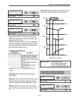
[Overload Warning]
FU1-56: Overload Trip Selection
FU1-57: Overload Trip Level
FU1-58: Overload Trip Delay Time
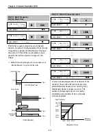
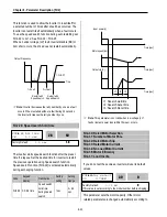
Inverter cuts off its output and displays fault message
when the output current persists over the FU1-57
[Overload Trip Level] for the time of FU1-58 [Overload Trip
Time]. This function protects the inverter and motor from
abnormal load conditions.
☞
Note:
The set value is the percentage of FU2-33 [Rated
Motor Current].
[Overload Trip Operation]
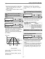
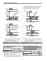
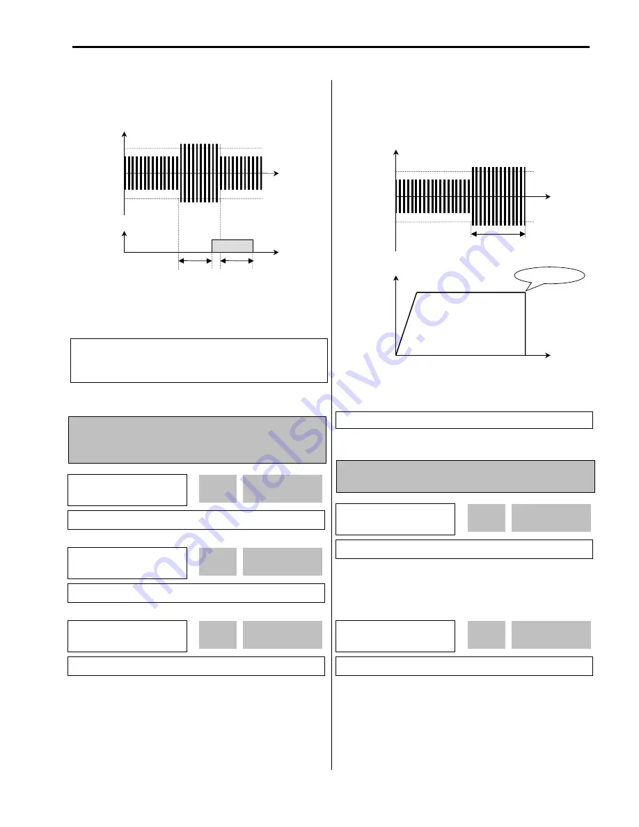
FU1-59: Stall Prevention Mode Selection (Bit set)
FU1-60: Stall Prevention Level
This bit set parameter follows the conventions used in I/O-
15 and I/O-16 to show the ON (bit set) status.
This function is used to prevent the motor from stalling by
reducing the inverter output frequency until the motor
current decreases below the stall prevention level. This
function can be selected for each mode of acceleration,
steady speed, and deceleration via bit combination.
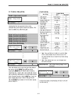
t1: FU1-55 [Overload Warning Time]
Output Current
Time
Time
FU1-54
[OL Level]
FU1-54
[OL Level]
AXA-AXC
ON
t1
t1
Related Functions:
FU2-33 [Rated Motor Current]
I/O-44 [Multi-function Auxiliary Contact
Output]
FU1
►
OLT select
56 --- Yes ---
1
56
Factory Default:
Yes
1
FU1
►
OLT level
57 180 %
180
57
Factory Default:
180 %
180
FU1
►
OLT time
58 60.0 sec
60.0
58
Factory Default:
60.0 sec
60.0
Output Current
Time
Time
FU1-57
[OLT Level]
FU1-57
[OLT Level]
Output Frequency
FU1- 58 [OLT Time]
Overload Trip
Related Functions:
FU2-33 [Rated Motor Current]
FU1
►
Stall prev.
59 000
000
59
Factory Default:
000
000
FU1
►
Stall level
60 180 %
180
60
Factory Default:
180 %
180
Summary of Contents for 30 HP30
Page 6: ......
Page 12: ......
Page 16: ...Chapter 1 Installation 1 4 BLANK ...
Page 18: ...Chapter 1 Installation 1 6 BLANK ...
Page 28: ...Chapter 1 Installation 1 16 Notes ...
Page 39: ...Chapter 2 Operation 2 11 Notes ...
Page 40: ......
Page 46: ......
Page 60: ...Chapter 4 Operation Examples 4 14 Notes ...
Page 83: ...Chapter 5 Parameter List 5 23 Notes ...
Page 84: ......
Page 92: ...Chapter 6 Parameter Description DRV 6 8 Notes ...
Page 105: ......
Page 106: ...Chapter 6 Parameter description FU1 6 14 Notes ...
Page 126: ...Chapter 6 Parameter Description FU2 6 34 Notes ...
Page 144: ...Chapter 6 Parameter Description I O 6 52 Notes ...
Page 162: ......
Page 188: ...Chapter 7 Options 7 26 Type 1 Max 400 Watt Type 2 Max 600 Watt A ...
Page 189: ...Chapter 7 Options 7 27 Type 3 ...
Page 194: ......
Page 204: ......
Page 210: ......


