Chapter 6 - Parameter Description [APP]
6-65
When the Flo
increse
When the Flo
decrese
Start
Stop
Aux. Motor
Start/Stop
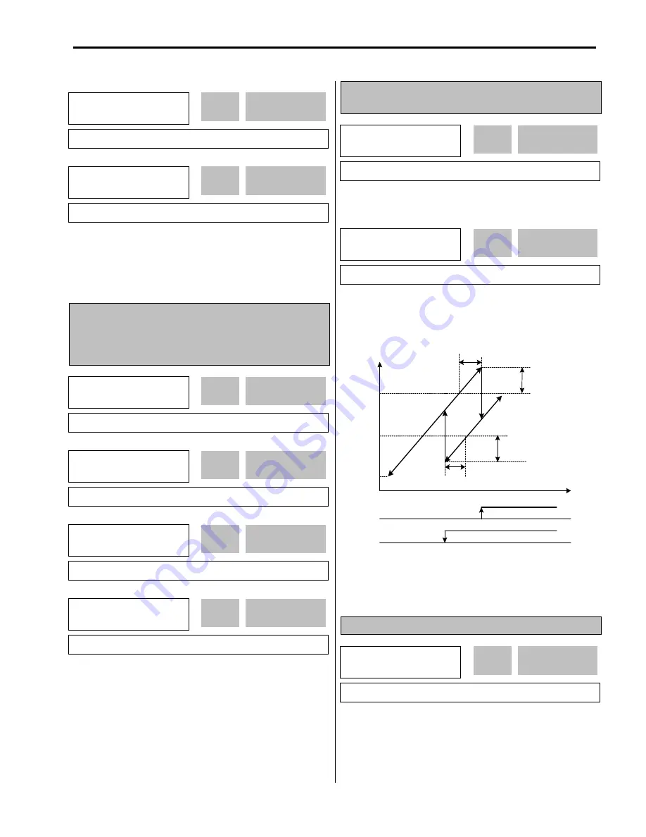
Frequency rise according to
APP-19
Output
Frequency
Aux start DT(APP-19)
Stop freq
1(APP-15)
Starting
Freq.
Aux stop DT(APP-20)
Frequency drop according to
APP-20
Flow
Start freq 1
(APP-11)
The inverter turns on AUX, RLY1, RLY2, and RLY3 in
order if the output frequency is over the frequencies set in
APP-11 to APP-14, respectively, and the time is over APP-
19.
APP-15: Stop Frequency of Aux. Motor 1
APP-16: Stop Frequency of Aux. Motor 2
APP-17: Stop Frequency of Aux. Motor 3
APP-18: Stop Frequency of Aux. Motor 4
The inverter turns off RLY3, RLY2, RLY1, and AUX in
order if the output frequency is below the frequencies set
in APP-15 to APP-18, respectively, and the time is over
APP-20.
APP-19: Delay Time before Operating Aux. Motor
APP-20: Delay Time before Stopping Aux. Motor
Sets the time the inverter waits before starting the auxiliary
motors.
Sets the time the inverter waits before stopping the
auxiliary motors.
[Aux. Motor Start/Stop with MMC]
APP-21: The Number of Aux. Motors
Sets the number of auxiliary motors connected to the
inverter.
APP
►
Start freq3
13 49.99 Hz
49.99
13
Factory Default:
49.99
Hz
49.99
APP
►
Start freq4
14 49.99 Hz
49.99
14
Factory Default:
49.99
Hz
49.99
APP
►
Stop freq1
15 15.00 Hz
15.00
15
Factory Default:
15.00
Hz
15.00
APP
►
Stop freq2
16 15.00 Hz
15.00
16
Factory Default:
15.00
Hz
15.00
APP
►
Stop freq3
17 15.00 Hz
15.00
17
Factory Default:
15.00
Hz
15.00
APP
►
Stop freq4
18 15.00 Hz
15.00
18
Factory Default:
15.00
Hz
15.00
APP
►
Aux Start DT
19 60.0 sec
60.0
19
Factory Default:
60.0
sec
60.0
APP
►
Aux Stop DT
20 60.0 sec
60.0
20
Factory Default:
60.0
sec
60.0
APP
►
Nbr Aux’s
21 4
4
21
Factory Default:
4
4
Summary of Contents for 30 HP30
Page 6: ......
Page 12: ......
Page 16: ...Chapter 1 Installation 1 4 BLANK ...
Page 18: ...Chapter 1 Installation 1 6 BLANK ...
Page 28: ...Chapter 1 Installation 1 16 Notes ...
Page 39: ...Chapter 2 Operation 2 11 Notes ...
Page 40: ......
Page 46: ......
Page 60: ...Chapter 4 Operation Examples 4 14 Notes ...
Page 83: ...Chapter 5 Parameter List 5 23 Notes ...
Page 84: ......
Page 92: ...Chapter 6 Parameter Description DRV 6 8 Notes ...
Page 105: ......
Page 106: ...Chapter 6 Parameter description FU1 6 14 Notes ...
Page 126: ...Chapter 6 Parameter Description FU2 6 34 Notes ...
Page 144: ...Chapter 6 Parameter Description I O 6 52 Notes ...
Page 162: ......
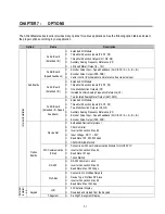
Page 188: ...Chapter 7 Options 7 26 Type 1 Max 400 Watt Type 2 Max 600 Watt A ...
Page 189: ...Chapter 7 Options 7 27 Type 3 ...
Page 194: ......
Page 204: ......
Page 210: ......


