Chapter 8 - Troubleshooting & Maintenance
8-3
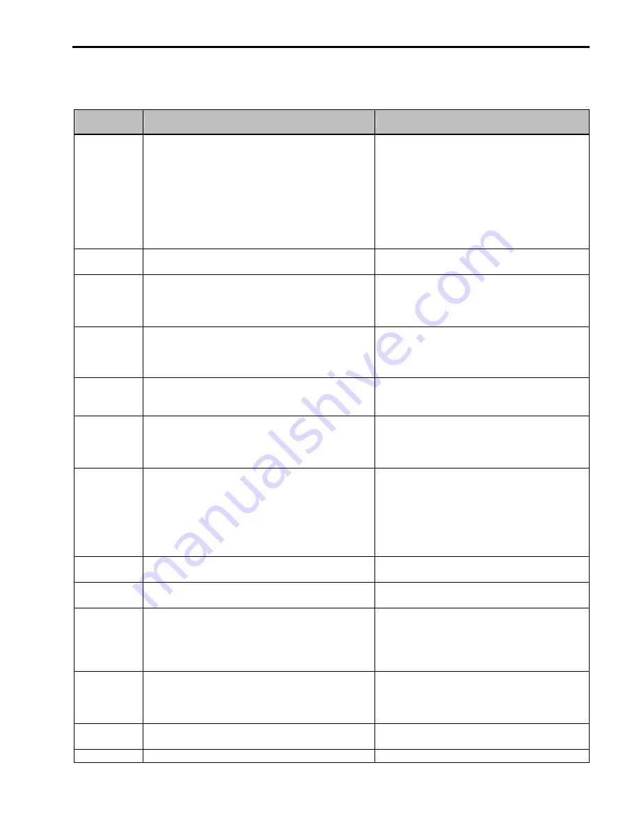
8.2 Fault Remedy
Protective
Function
Cause
Remedy
Over Current
Protection
1) Acceleration/Deceleration time is too short compared to
the GD
²
of the load
2) Load is larger than the inverter rating
3) Inverter turns output on when the motor is free running.
4) Output short or ground fault has occurred
5) Mechanical brake of the motor is operating too fast
6) Components of the main circuit have overheated due
to a faulty cooling fan
1) Increase Accel/Decel time
2) Increase inverter capacity.
3) Operate after motor has stopped
4) Check output wiring
5) Check mechanical brake operation
6) Check cooling fan
(Caution)
Operating inverter prior to correcting fault
may damage the IGBT
Ground Current
Protection
1) Ground fault has occurred at the output wiring of inverter.
2) The insulation of the motor is damaged due to heat.
1) Investigate the output wiring of inverter
2) Exchange motor
Over Voltage
Protection
1) Acceleration time is too short compared to the GD
²
of
load
2) Regenerative load at the output
3) Line voltage high
1) Increase deceleration time
2) Use regenerative resistor option
3) Check line voltage
Current Limit
Protection
(Overload
Protection)
1) Load is larger than the inverter rating
2) Selected incorrect inverter capacity
3) Set incorrect V/F pattern
1) Increase capacity of motor and inverter
2) Select correct inverter capacity
3) Select correct V/F pattern
Fuse Damage
1) Damage due to repeated over current protection
2) Damage due to instant deceleration when motor is at an
excessive excitation status.
Exchange the fuse
(Caution)
The IGBT receives damages on many
occasions when Fuse Open Trip occurs
Heat Sink
Overheat
1) Cooling fan damaged or an alien substance inserted
2) Cooling system has faults
3) Ambient temperature high
1) Exchange cooling fans and/or eliminate alien
substance
2) Check for alien substances in the heat sink
3) Keep ambient temperature under 40
℃
Electronic
Thermal
1) Motor has overheated
2) Load is larger than inverter rating
3) ETH level too low
4) Selected incorrect inverter capacity
5) Set incorrect V/F pattern
6) Operated too long at low speeds
1) Reduce load and/or running duty
2) Increase inverter capacity
3) Adjust ETH level to an appropriate level
4) Select correct inverter capacity
5) Select correct V/F pattern
6) Install a cooling fan with a separate power supply
Ext Trip-A
External fault has occurred
Eliminate fault at circuit connected to external fault
terminal or cause of external fault input
Ext Trip-B
External fault has occurred
Eliminate fault at circuit connected to external fault
terminal or cause of external fault input
Low Voltage
Protection
1) Line voltage low
2) Load larger than line capacity is connected to line
(welding machine, motor with high starting current
connected to the commercial line)
3) Faulty magnetic switch at the input side of the inverter
1) Check line voltage
2) Increase line capacity
3) Exchange magnetic switch
Over Current 2
1) Short has occurred between the upper and lower IGBT.
2) Short has occurred at the output of the inverter
3) Acceleration/Deceleration time is too short compared to
the GD
²
of load
1) Check IGBT
2) Check output wiring of inverter
3) Increase acceleration time
Output Phase
Open
1) Faulty contact of magnetic switch at output
2) Faulty output wiring
1) Check magnetic switch at output of inverter
2) Check output wiring
Over Speed 1) Faulty wiring of Encoder (A, B)
1) Check Encoder A, B signal wiring and wire them
Summary of Contents for 30 HP30
Page 6: ......
Page 12: ......
Page 16: ...Chapter 1 Installation 1 4 BLANK ...
Page 18: ...Chapter 1 Installation 1 6 BLANK ...
Page 28: ...Chapter 1 Installation 1 16 Notes ...
Page 39: ...Chapter 2 Operation 2 11 Notes ...
Page 40: ......
Page 46: ......
Page 60: ...Chapter 4 Operation Examples 4 14 Notes ...
Page 83: ...Chapter 5 Parameter List 5 23 Notes ...
Page 84: ......
Page 92: ...Chapter 6 Parameter Description DRV 6 8 Notes ...
Page 105: ......
Page 106: ...Chapter 6 Parameter description FU1 6 14 Notes ...
Page 126: ...Chapter 6 Parameter Description FU2 6 34 Notes ...
Page 144: ...Chapter 6 Parameter Description I O 6 52 Notes ...
Page 162: ......
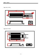
Page 188: ...Chapter 7 Options 7 26 Type 1 Max 400 Watt Type 2 Max 600 Watt A ...
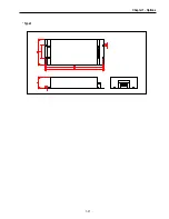
Page 189: ...Chapter 7 Options 7 27 Type 3 ...
Page 194: ......
Page 204: ......
Page 210: ......

