Chapter 1 - Installation
1-9
1.7.1
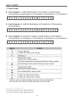
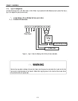
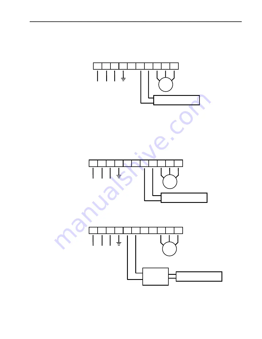
Type A Configuration
As standard on the ACtionMaster inverter, this type of configuration has internal dynamic braking resistor of 3% ED. When
an application requires more braking duty, an external dynamic braking resistor may be connected instead of the internal
resistor.
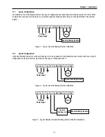
R S T G N B1 B2 U V W
Figure 1 – Type A Dynamic Braking Resistor Installation
1.7.2
Type B Configuration
A Dynamic Braking Resistor or a Dynamic Braking Unit may be added to ACtionMaster series inverters that have a Type B
configuration power terminal strip. As standard, this type of configuration has in
R S T G P N B1 B2 U V W
Figure 2 – Type B Dynamic Braking Resistor Installation
R S T G P N B1 B2 U V W
Figure 3 – Type B Additional Dynamic Braking Unit and Resistor Installation
Motor
Dynamic Braking Resistor
3 Phase
Power Input
Motor
3 Phase
Power Input
Dynamic Braking Resistor
Motor
3 Phase
Power Input
Dynamic Braking Resistor
Dynamic
Braking Unit
Summary of Contents for 30 HP30
Page 6: ......
Page 12: ......
Page 16: ...Chapter 1 Installation 1 4 BLANK ...
Page 18: ...Chapter 1 Installation 1 6 BLANK ...
Page 28: ...Chapter 1 Installation 1 16 Notes ...
Page 39: ...Chapter 2 Operation 2 11 Notes ...
Page 40: ......
Page 46: ......
Page 60: ...Chapter 4 Operation Examples 4 14 Notes ...
Page 83: ...Chapter 5 Parameter List 5 23 Notes ...
Page 84: ......
Page 92: ...Chapter 6 Parameter Description DRV 6 8 Notes ...
Page 105: ......
Page 106: ...Chapter 6 Parameter description FU1 6 14 Notes ...
Page 126: ...Chapter 6 Parameter Description FU2 6 34 Notes ...
Page 144: ...Chapter 6 Parameter Description I O 6 52 Notes ...
Page 162: ......
Page 188: ...Chapter 7 Options 7 26 Type 1 Max 400 Watt Type 2 Max 600 Watt A ...
Page 189: ...Chapter 7 Options 7 27 Type 3 ...
Page 194: ......
Page 204: ......
Page 210: ......


