


Chapter 6 - Parameter Description [FU2]
6-26
SL I-gain is the integral gain of speed controller. If this
value is set low, you can get better transient response
characteristic and steady state characteristic. However, if
this value is set too low, there may be an overshoot in
speed control.
☞
Note:
The response time of a system is affected by the load
inertia. For better control performance, set the FU2-37
[Load Inertia] correctly.
FU2-47: PID Operation Selection
This code selects the PID control.
For HVAC or Pump applications, the PID control can be
used to adjust the actual output by comparing a feedback
with a ‘Set-point’ given to the inverter. This ‘Set-point’ can
be in the form of Speed, Temperature, Pressure, Flow
level, etc. The ‘Set-point’ and the feedback signals are
provided externally to the inverter analog input terminals
V1, V2 or I. The inverter compares the signals in
calculating ‘total-error’ which is reflected in the inverter
output.
Please see FU2-50 to FU2-54 for more detail.
☞
Note:
PID control can be bypassed to manual operation
temporarily by defining one of the multifunction input
terminals (P1~P3) to “Open-loop”. The inverter will change
to manual operation from PID control when this terminal is
ON, and change back to PID control when this terminal is
OFF.
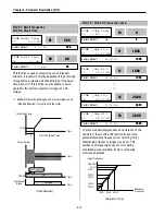
FU2-48: PID Reference Frequency Selection
FU2-49: PID Reference Mode Selection
FU2-50: PID Output Direction Selection
This code selects reference frequency for PID control.
[Ramp Freq]: PID control references frequency with Accel
and Decel pattern and time.
[Target Freq]: PID control references frequency without
Accel and Decel pattern and time.
This code selects reference input for PID control.
[Freq Mode]: PID control references signal set in DRV-04.
When selected other than ‘Freq mode’, PID control
references the selected signal regardless the selection in
DRV-04.
This code selects the direction of output value of PID
controller. The output value is added to reference
frequency.
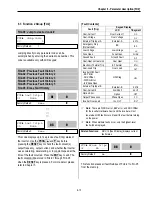
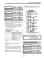
FU2
►
SL I-gain
46 3276
3276
46
Factory Default:
3276
3276
Related Functions:
FU2-30 ~ FU2-37 [Motor Parameters]
FU2-40 [Control Method]
FU2
►
Proc PI mode
47 --- No ---
0
47
Factory Default:
No
0
Related Functions:
DRV-04 [Frequency Mode]
I/O-01 to I/O-10 [Analog Signal Setting]
I/O-12 to I/O-14 [Multi-Function Input]
EXT-15 to EXT-21 [Pulse Input Setting]
FU2-50 to FU2-54 [PID Feedback]
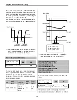
FU2
►
PID Ref
48 Ramp freq.
0
48
Factory Default:
No
0
FU2
►
PID Ref Mode
49 Freq mode
0
49
Factory Default:
Freq mode
0
FU2
►
PID Out Dir
50 Ramp Freq.
0
50
Factory Default:
Ramp Freq.
0
Summary of Contents for 30 HP30
Page 6: ......
Page 12: ......
Page 16: ...Chapter 1 Installation 1 4 BLANK ...
Page 18: ...Chapter 1 Installation 1 6 BLANK ...
Page 28: ...Chapter 1 Installation 1 16 Notes ...
Page 39: ...Chapter 2 Operation 2 11 Notes ...
Page 40: ......
Page 46: ......
Page 60: ...Chapter 4 Operation Examples 4 14 Notes ...
Page 83: ...Chapter 5 Parameter List 5 23 Notes ...
Page 84: ......
Page 92: ...Chapter 6 Parameter Description DRV 6 8 Notes ...
Page 105: ......
Page 106: ...Chapter 6 Parameter description FU1 6 14 Notes ...
Page 126: ...Chapter 6 Parameter Description FU2 6 34 Notes ...
Page 144: ...Chapter 6 Parameter Description I O 6 52 Notes ...
Page 162: ......
Page 188: ...Chapter 7 Options 7 26 Type 1 Max 400 Watt Type 2 Max 600 Watt A ...
Page 189: ...Chapter 7 Options 7 27 Type 3 ...
Page 194: ......
Page 204: ......
Page 210: ......


