
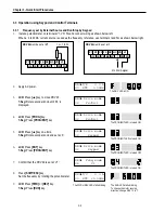
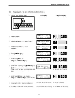

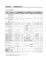
Chapter 4 – Function Settings
4-3
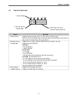
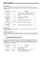
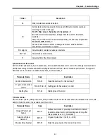
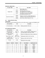
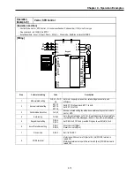
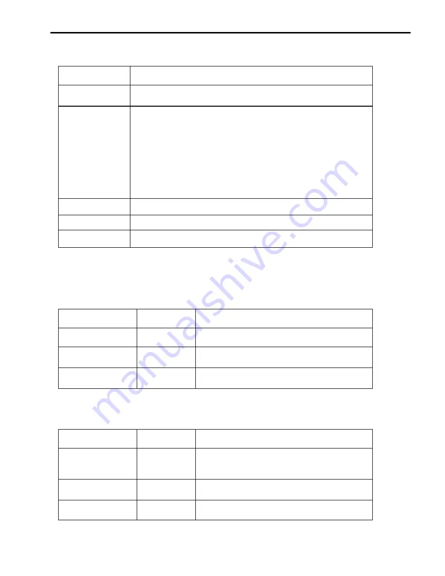
FU2-40
Description
No
Motor constants calculation disabled
All
All constants can be measured in this code but different constants are tuned
according to control mode type;
For V/F, Slip compen , Sensorless_S, Sensorless_T:
(No-load current, stator resistance, leakage inductance, stator inductance
available)
Note) Only no-load current can be calculated during V/F and Slip compensation.
For Vector_SPD, Vector_T:
No-load current, stator resistance, leakage inductance, stator inductance,
encoder test, rotor filter time constant
Rs+Lsigma
Calculate stator resistance, leakage inductance
Enc Test
Calculate the encoder status
Tr
Calculate Rotor filter time constant
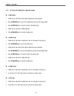
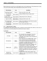
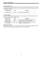
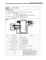
6) Sensorless vector control
Set FU2-39 to 2 {Sensorless_S} or 3 {Sensorless_T} to enable Sensorless vector control. It is strongly recommended to
perform Auto-tuning for Sensorless before starting Sensorless control in order to maximize performance. Two types of
Sensorless vector control are available; Sensorless_S or Sensorless_T.
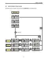
Parameter Name
Code
Description
Control mode selection
FU2-39
Select Sensorless_S or Sensorless_T
P, I gain for sensorless
control
FU2-45, FU2-46 Setting gain for Sensorless_S control
Starting freq
FU1-22
Starting freq of the motor
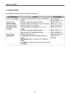
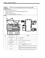
7) Vector control
Set FU2-39 to 4 {Vector_SPD} or 5{Vector_TRQ} to enable Vector control. Encoder should be installed to the motor with
Sub-B or Sub-D boards in the inverter to start this control.
Parameter Name
Code
Description
Usage of Pulse Input
Signal
EXT-12
Defines the method of pulse input with SUB-B or SUB-D
boards mounted. Vector control setting is valid only after
this parameter is set to 1 {Feed-back}.
Pulse Input Signal
Selection
EXT-15
3 types of pulse input : (A+B), A, -(A+B)
Encoder Pulse Number
EXT-16
Enter the pulse number of encoder in the motor.
Summary of Contents for 30 HP30
Page 6: ......
Page 12: ......
Page 16: ...Chapter 1 Installation 1 4 BLANK ...
Page 18: ...Chapter 1 Installation 1 6 BLANK ...
Page 28: ...Chapter 1 Installation 1 16 Notes ...
Page 39: ...Chapter 2 Operation 2 11 Notes ...
Page 40: ......
Page 46: ......
Page 60: ...Chapter 4 Operation Examples 4 14 Notes ...
Page 83: ...Chapter 5 Parameter List 5 23 Notes ...
Page 84: ......
Page 92: ...Chapter 6 Parameter Description DRV 6 8 Notes ...
Page 105: ......
Page 106: ...Chapter 6 Parameter description FU1 6 14 Notes ...
Page 126: ...Chapter 6 Parameter Description FU2 6 34 Notes ...
Page 144: ...Chapter 6 Parameter Description I O 6 52 Notes ...
Page 162: ......
Page 188: ...Chapter 7 Options 7 26 Type 1 Max 400 Watt Type 2 Max 600 Watt A ...
Page 189: ...Chapter 7 Options 7 27 Type 3 ...
Page 194: ......
Page 204: ......
Page 210: ......


