Chapter 8 - Troubleshooting & Maintenance
8-2
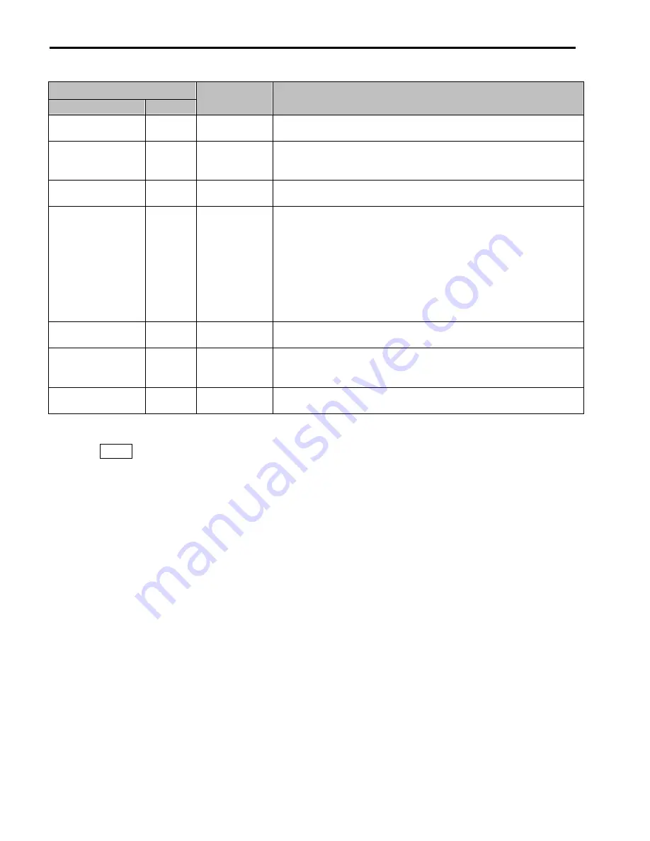
Keypad Display
LCD
7-Segment
Protective
Function
Description
Option (**)
OPT
Option Fault
Fault at the internal option of the inverter.
HW-Diag HW
Inverter H/W
Fault
A fault signal is output when an error occurs to the control circuitry of the
inverter. There are the Wdog error, the EEP error, and the ADC Offset for this
fault
COM Error
CPU Error
Err
Communication
Error
This fault is displayed when the inverter cannot communicate with the keypad.
LOP
LOR
LOV
LOI
LOX
LP
LR
LV
LI
LX
Operating Method
when the
Frequency
Reference is Lost
According to the I/O-48 [Operating Method when the Frequency Reference is
Lost] setting, there are three modes: continue operation, decelerate and stop,
and free run,
LOP: Displayed when option frequency reference is lost (DPRAM time out)
LOR:
Displayed when option frequency reference is lost (Communication
network fault)
LOV: Displayed when ‘V1’ analog frequency reference is lost.
LOI: Displayed when ‘I‘ analog frequency reference is lost.
LOX: Displayed when sun-board (V2, ENC) analog frequency reference is lost.
Inv. OLT
IOLT
Inverter Overload
The inverter turns off its output when the output current of the inverter flows
more than the rated level (150% for 1 minute, 200% for 0.5 seconds).
NTC open
NTC
Thermal Sensor
Opened
Inverter uses NC thermal sensor for detecting heat sink temperature. If this
message is displayed, the thermal sensor wire may be cut. (Inverter keeps
operating)
MC Fail
MCF
Magnetic
contactor fault
This fault is displayed when input power is not applied or M/C inside the inverter
becomes faulty.
To reset fault perform
one
of the following:
}
Press
RESET
key on the keypad.
}
Close RST-CM terminals.
}
Cycle power to the inverter.
If a problem persists, please contact the factory or your local distributor.
Summary of Contents for 30 HP30
Page 6: ......
Page 12: ......
Page 16: ...Chapter 1 Installation 1 4 BLANK ...
Page 18: ...Chapter 1 Installation 1 6 BLANK ...
Page 28: ...Chapter 1 Installation 1 16 Notes ...
Page 39: ...Chapter 2 Operation 2 11 Notes ...
Page 40: ......
Page 46: ......
Page 60: ...Chapter 4 Operation Examples 4 14 Notes ...
Page 83: ...Chapter 5 Parameter List 5 23 Notes ...
Page 84: ......
Page 92: ...Chapter 6 Parameter Description DRV 6 8 Notes ...
Page 105: ......
Page 106: ...Chapter 6 Parameter description FU1 6 14 Notes ...
Page 126: ...Chapter 6 Parameter Description FU2 6 34 Notes ...
Page 144: ...Chapter 6 Parameter Description I O 6 52 Notes ...
Page 162: ......
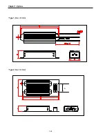
Page 188: ...Chapter 7 Options 7 26 Type 1 Max 400 Watt Type 2 Max 600 Watt A ...
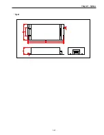
Page 189: ...Chapter 7 Options 7 27 Type 3 ...
Page 194: ......
Page 204: ......
Page 210: ......

